
Material conveying equipment and material conveying method

A material conveying and equipment technology, applied in the field of material conveying equipment, can solve problems such as easy tilting of materials to be conveyed, manual participation, and influence on the smoothness of conveying

Active Publication Date: 2020-08-18
SUZHOU BECKE ELECTRIC TECH CO LTD
View PDF5 Cites 0 Cited by
  • Summary
  • Abstract
  • Description
  • Claims
  • Application Information

AI Technical Summary

Problems solved by technology

[0007] How to solve the problem of easy inclination and offset of the materials to be transported during the material transport process based on the synchronous and stable transport mode, so as not to greatly affect the smoothness of the transport, and to solve the automation of the pick-and-place operation of the materials to be transported Low, and a lot of manual participation is required, so as not to greatly affect the convenience of pick-and-place operations

Method used


Image

  • Material conveying equipment and material conveying method
  • Material conveying equipment and material conveying method

Examples


Embodiment Construction

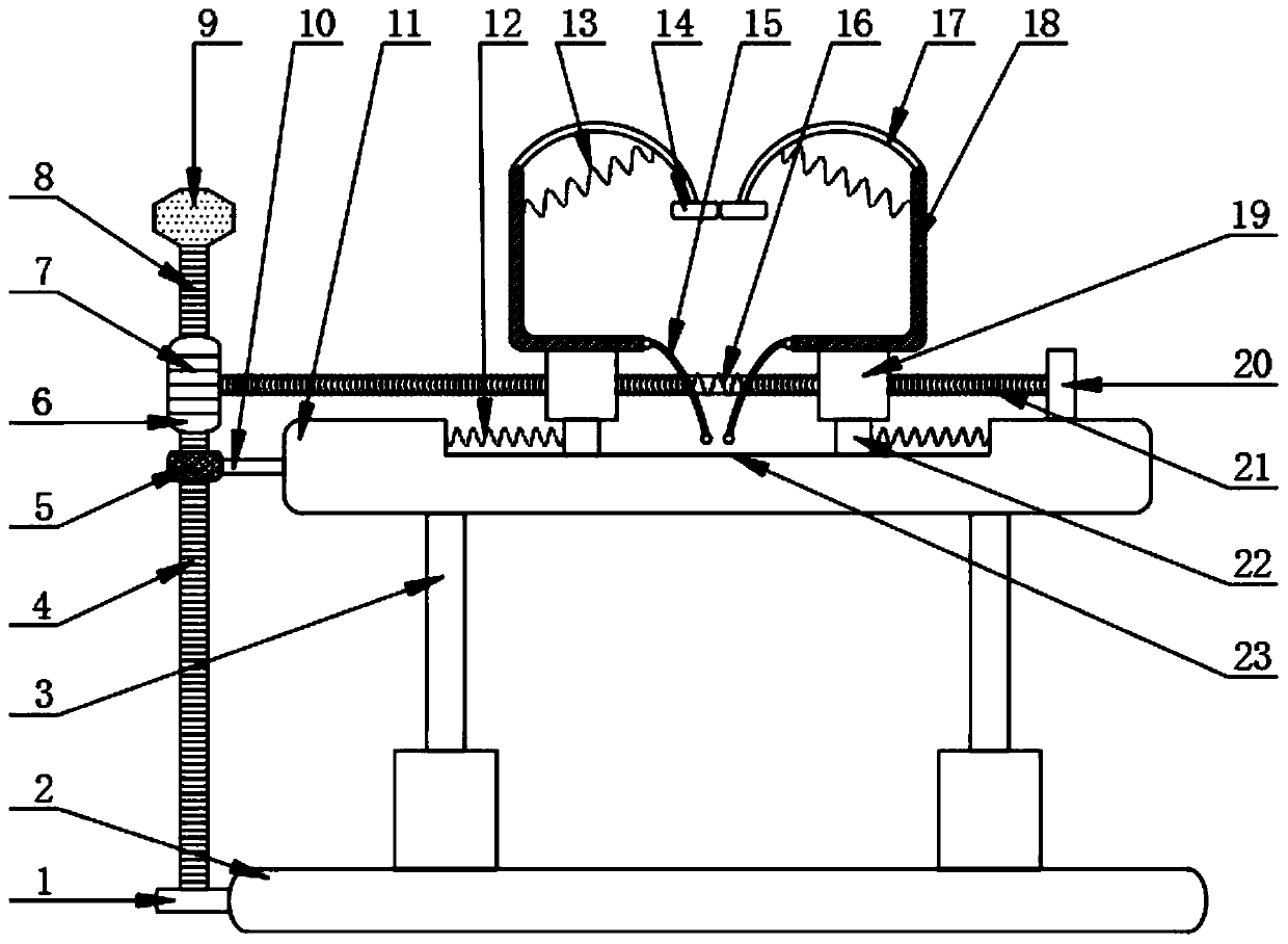
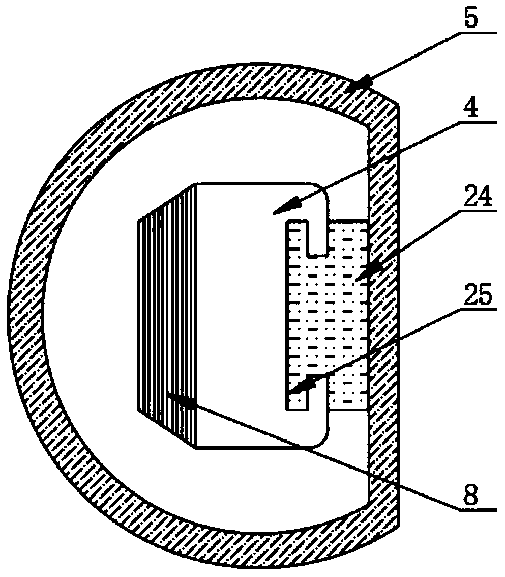
[0027] Such as Figure 1-2 As shown, the conveying equipment includes support block 1, bottom plate 2, electric push rod 3, column 4, collar 5, knob 6, first tooth groove 7, second tooth groove 8, wear-resistant rubber block 9, connecting rod 10. Fixed plate 11, first telescopic spring 12, second telescopic spring 13, pad 14, first elastic rod 15, third telescopic spring 16, second elastic rod 17, L-shaped splint 18, threaded sleeve 19, Block 20, threaded rod 21, slide block 22, chute 23, block 24 and draw-in groove 25, the top of bottom plate 2 is evenly provided with electric push rod 3, and the top of electric push rod 3 is fixed with fixed plate 11 by bolt;

[0028]The top center of the fixed plate 11 is provided with a chute 23, the inside of the chute 23 is correspondingly equipped with a slide block 22, and a second side wall is fixed by spot welding between one side of the slide block 22 and the adjacent side inner wall of the chute 23. A telescopic spring 12, the top...


PUM


Abstract

The invention discloses material conveying equipment and a material conveying method. The material conveying equipment comprises a supporting block, a baseplate, electric push rods, a vertical column,a sleeve ring, a knob, a first toothed groove, a second toothed groove, an abrasion-resisting rubber block, a connecting rod, a fixing plate, first telescopic springs, second telescopic springs, cushion blocks, first elastic rods, a third telescopic spring, second elastic rods, L-shaped clamping plates, threaded sleeves, a stop block, threaded rods, sliding blocks, a sliding groove, a clamping block and a clamping groove, wherein the electric push rods are uniformly arranged at the top of the baseplate; and the fixing plate is fixed at the top ends of the electric push rods through bolts. According to the synchronous conveying method based on the cooperation between the clamping block and the clamping groove, between the vertical column and the knob, and between the threaded sleeves and the threaded rods as well as the synchronous conveying method based on the fact that the upper-lower surfaces and two side surfaces of a to-be-conveyed material are gradually clamped, the still-existing problem that the to-be-conveyed material is easy to tilt and deviate can be solved, and the conveying stationarity can be greatly improved.

Description

technical field [0001] The invention relates to the technical field of conveying equipment, in particular to conveying equipment and a conveying method. Background technique [0002] In the document whose publication number is CN109205176A, the aluminum alloy materials of different sizes are only blocked according to the movable baffle plate, so as to prevent the material from falling downward during the climbing process of conveying materials, so that the plates can be conveyed in an orderly manner. And according to the buffer protection pad to protect the conveying aluminum alloy material, prevent the outer surface of the conveyor belt from being damaged, greatly prolonging the service life of the conveyor belt, and the second movable support rod of the conveying device is carried out by the set extension rod Extended so that it can be adapted to different working heights; [0003] However, in the process of conveying materials, there are still situations where the materi...

Claims


Application Information

Patent Timeline
IPC IPC(8): B65G47/74
CPCB65G47/74
Inventor 桑配青
Owner SUZHOU BECKE ELECTRIC TECH CO LTD
Learn More