
Check fixture

A fixture and side support technology, which is applied in the direction of instruments, measuring devices, electronic circuit testing, etc., can solve the problems that the probe 40X is easy to wear and the service life of the probe 40X is shortened, so as to avoid wear, prolong the service life, reduce the wear effect

Active Publication Date: 2019-10-11
尼得科精密检测设备(浙江)有限公司
View PDF16 Cites 0 Cited by
  • Summary
  • Abstract
  • Description
  • Claims
  • Application Information

AI Technical Summary

Problems solved by technology

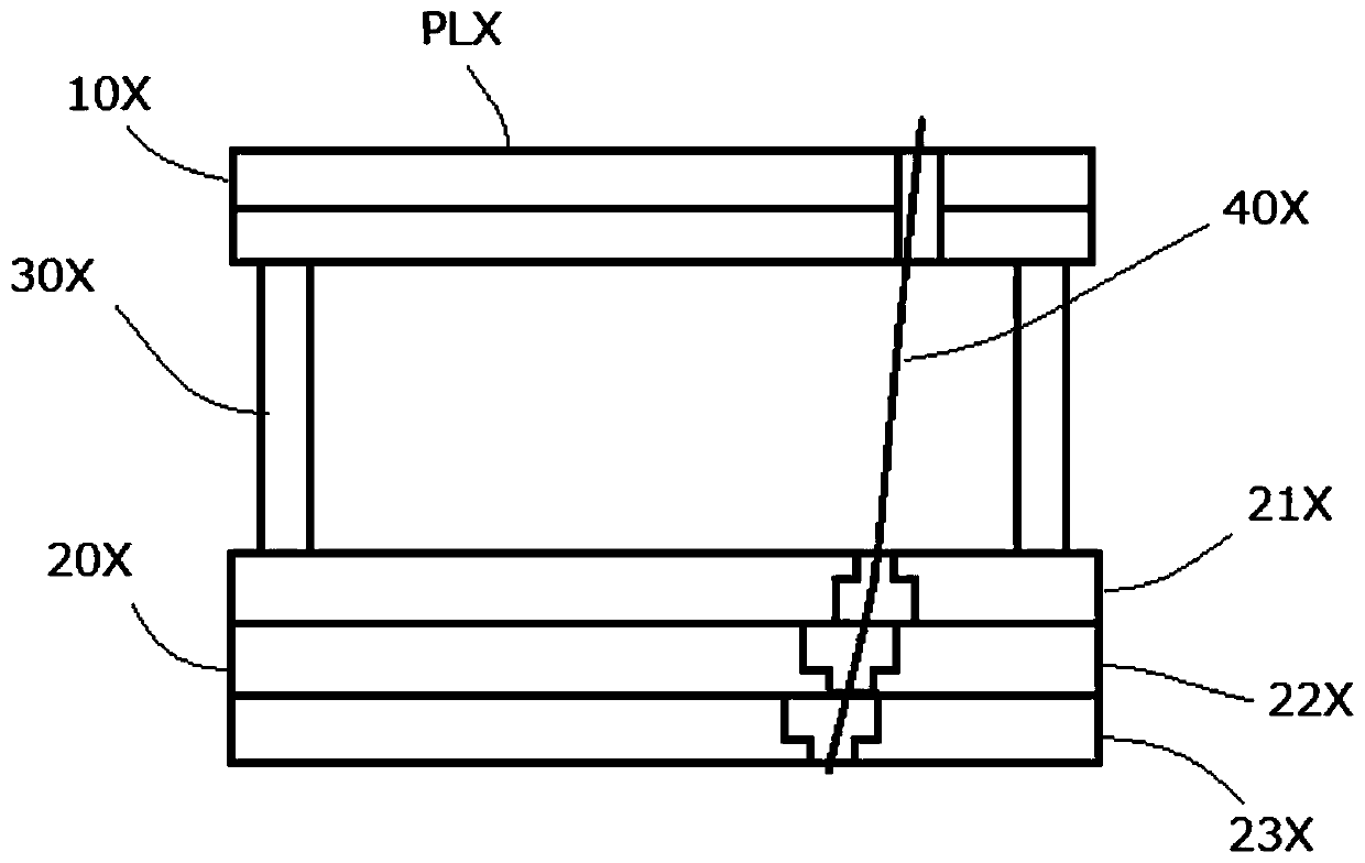
[0007] However, in actual use, it is found that the probe 40X is prone to wear at the through hole of the electrode-side support plate 21X closest to the inspection-side support 10X, resulting in a shortened service life of the probe 40X

Method used


Image

  • Check fixture
  • Check fixture
  • Check fixture

Examples


Embodiment Construction

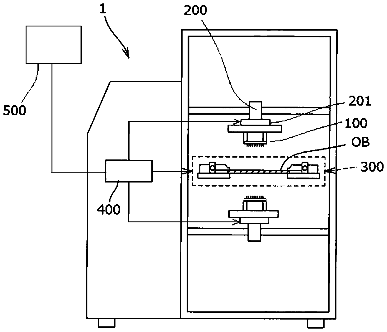
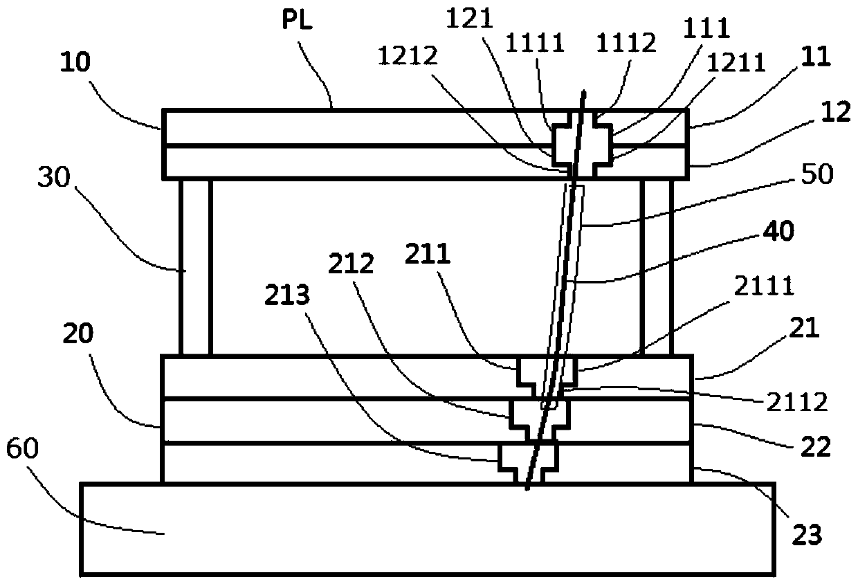
[0055] Below, combine figure 1 and figure 2 , an inspection device having an inspection jig according to an embodiment of the present invention is described, wherein, figure 1 is an overall configuration diagram schematically showing an inspection device having an inspection jig according to an embodiment of the present invention, figure 2 is a diagram schematically showing an inspection jig according to an embodiment of the present invention, and shows figure 1 Check the upper inspection jig in the middle.

[0056] Such as figure 1 As shown, the inspection device 1 includes: an inspection fixture 100; a moving mechanism 200, the moving mechanism 200 is used to move the inspection fixture 100, and the moving mechanism 200 has a fixture installation part 201, and the fixture installation part 201 is used to install the inspection fixture 100 (Specifically, it supports the following electrode mounting part 60 of the inspection jig 100); a transport mechanism (not shown...


PUM


Abstract

The inspection fixture of this invention helps ensure the contact accuracy of the front end of a probe with the inspection point of an inspection object, and extends the life of the probe. The inspection fixture of the present invention comprises: an inspection side support having an abutting surface abutting against the inspection object; an electrode side support spaced apart from the inspectionside support; and a plurality of flexible probes. The flexible probes, the base ends of which are connected to the electrode, and the front ends of which protrude from the abutting surface to be in contact with the inspection object, penetrate through the electrode side support and the inspection side support. The electrode side support has a plurality of electrode side support plates arranged inthe arranged direction of the inspection side support and the electrode side support, and each of the electrode side support plates has a first through hole for the probes to penetrate. The first through hole of the electrode side support plate nearest to the inspection side support has a large diameter portion and a small diameter portion. The small diameter portion is apart from the inspectionside support than the large diameter portion, and the diameter of the small diameter portion is smaller than the diameter of the large diameter portion.

Description

technical field [0001] The invention relates to an inspection jig, in particular to an inspection jig used for electrical inspection of inspection objects such as circuit boards. Background technique [0002] In the past, when conducting electrical inspections such as short circuits and open circuits on circuit boards with many solder joints used in miniaturized electronic products (such as mobile phones, notebook computers, etc.), inspection devices often use multiple wires. Inspection fixture for probes. [0003] The above-mentioned inspection jig usually has the following image 3 The structure shown, that is to say, includes: an inspection-side support 10X having a contact surface PLX (sometimes called a loading surface) that abuts against an inspection object; The electrode side support body 20X; the connecting member 30X connecting the inspection side support body 10X and the electrode side support body 20X; contacting the electrode side support body 20X and being arr...

Claims


Application Information

Patent Timeline
Patent Type & Authority Patents(China)
IPC IPC(8): G01R1/04G01R1/073G01R31/28
Inventor 木津卓也李俊华何幼峰
Owner 尼得科精密检测设备(浙江)有限公司
Learn More