
Electronic component pin bending equipment

A technology for electronic components and pins, applied in the field of electronic component pin bending equipment, can solve the problems of low pin bending accuracy, low pass rate, low efficiency, etc.

Inactive Publication Date: 2020-08-18
HANGZHOU RUJIAN ELECTRONICS EQUIP CO LTD
View PDF8 Cites 1 Cited by
  • Summary
  • Abstract
  • Description
  • Claims
  • Application Information

AI Technical Summary

Problems solved by technology

In the traditional process, manual bending is often performed manually using tools such as jigs. The bending speed is slow, the efficiency is low, and the labor cost is high, and the bending accuracy of the pins is low, the consistency is poor, and the pass rate is low. , so there is an urgent need for an electronic component pin bending equipment to solve the above problems, so as to adapt to the rapid development of the automation industry

Method used

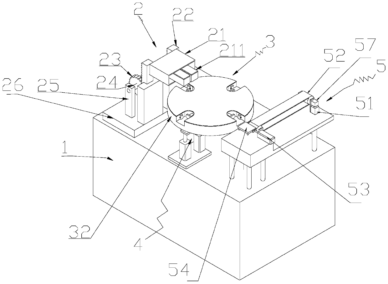

Image

  • Electronic component pin bending equipment
  • Electronic component pin bending equipment
  • Electronic component pin bending equipment

Examples


Embodiment Construction

[0038] The following will be combined with Figure 1 to Figure 17 The present invention is described in detail, and the technical solutions in the embodiments of the present invention are clearly and completely described. Apparently, the described embodiments are only some of the embodiments of the present invention, not all of them. Based on the embodiments of the present invention, all other embodiments obtained by persons of ordinary skill in the art without making creative efforts belong to the protection scope of the present invention.

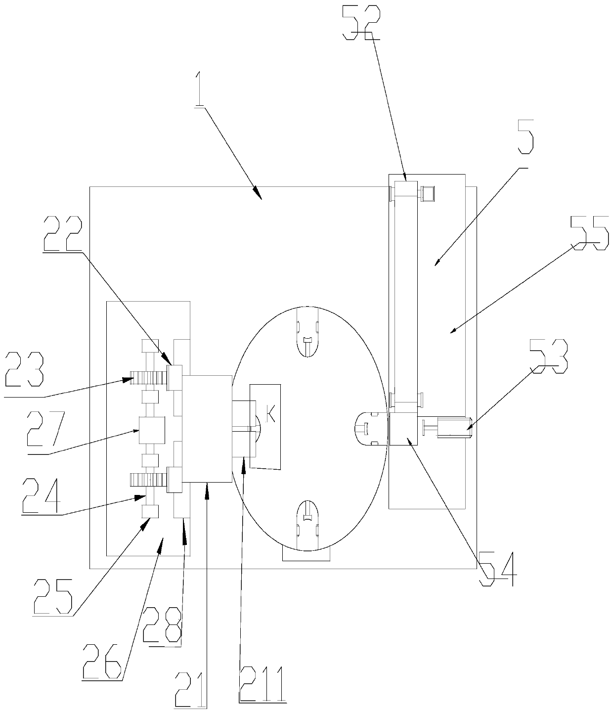
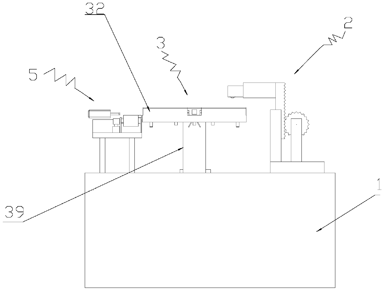
[0039] The present invention is a kind of bending equipment of electronic component lead, comprises electric control box 1, conveying device 5, is characterized in that: described a kind of electronic component lead bending equipment also comprises the fixing device 3 for fixing electronic component; The fixing device 3 includes a rotating shaft 39, a rotating fixed disk 32, a hydraulic pusher 33, a pressing baffle 38, a first compression...


PUM


Abstract

The invention relates to the field of electronic component manufacturing, in particular to electronic component pin bending equipment. The electronic component pin bending equipment comprises an electric cabinet and a conveying device, and also comprises a rotating shaft, a rotating fixed disc, a hydraulic pusher, a pressing baffle plate, a first compression spring, a compressor, a tension rod, aconnecting box fixedly arranged at the other end of the tension rod, a connecting block fixedly arranged on the bottom wall of the interior of the connecting box, and a thrust plate fixedly arranged at the lower end of the connecting box, and the tension rod is fixedly connected with the compressor; the hydraulic pusher comprises a first hydraulic push rod fixedly arranged at the bottom of the hydraulic pusher in the vertical direction, a second hydraulic push rod fixedly arranged on the side wall of the hydraulic pusher in the horizontal direction and a push block fixedly arranged at the other end of the second hydraulic push rod. According to the equipment, the bending precision of electronic component pin bending is improved, the consistency is high, the qualification rate is high, andthe equipment automation degree is high.

Description

technical field [0001] The invention relates to the field of electronic component manufacturing, in particular to an electronic component pin bending equipment. Background technique [0002] In the electronics and electrical industries, electronic components such as diodes, resistors, capacitors, and inductors are often used. In order to meet the needs of connecting with other parts or circuits, sometimes their pins need to be formed, that is, bent into the desired shape. . In the traditional process, manual bending is often performed manually using tools such as jigs. The bending speed is slow, the efficiency is low, and the labor cost is high, and the bending accuracy of the pins is low, the consistency is poor, and the pass rate is low. , so there is an urgent need for an electronic component pin bending equipment to solve the above problems, so as to adapt to the rapid development of the automation industry. Contents of the invention [0003] The purpose of the prese...

Claims


Application Information

Patent Timeline
Patent Type & Authority Applications(China)
IPC IPC(8): B21F1/00B21F23/00B65G47/82
CPCB21F1/004B21F23/00B65G47/82
Inventor 朱冬祥
Owner HANGZHOU RUJIAN ELECTRONICS EQUIP CO LTD
Learn More