
Automatic riveting device for hollow chain

A chain and hollow technology, applied in the field of automatic riveting head devices for hollow chains, can solve the problems of affecting the quality of chain riveting heads, unable to meet production schedule, low production efficiency, etc. Simple and effective

Pending Publication Date: 2021-12-03
苏州工业园区天地链条有限公司
View PDF0 Cites 0 Cited by
  • Summary
  • Abstract
  • Description
  • Claims
  • Application Information

AI Technical Summary

Problems solved by technology

[0002] The existing rivet head is an important process in the chain production process. The quality of the rivet head directly affects the firmness and service life of the chain. For hollow chains, it is extremely important. Due to the particularity of the hollow The riveting head equipment must use special equipment. At present, the commonly used riveting head equipment is a semi-automatic rocker arm riveting machine, which requires two workers to complete the work at the same time. One person is responsible for the entry and exit of the chain, and the other operates the semi-automatic rocker arm riveting machine. The equipment is a single-sided riveting head, the production efficiency is low, and it cannot meet the requirements of the production schedule. Moreover, due to the manual operation of the rocker arm, there are operational errors, that is, the different forces used by different workers will lead to different sizes of the riveting head, which will affect the quality of the chain riveting head.

Method used


Image

  • Automatic riveting device for hollow chain
  • Automatic riveting device for hollow chain
  • Automatic riveting device for hollow chain

Examples


Embodiment Construction

[0019] The following will clearly and completely describe the technical solutions in the embodiments of the present invention with reference to the accompanying drawings in the embodiments of the present invention. Obviously, the described embodiments are only some, not all, embodiments of the present invention. Based on the embodiments of the present invention, all other embodiments obtained by persons of ordinary skill in the art without making creative efforts belong to the protection scope of the present invention.

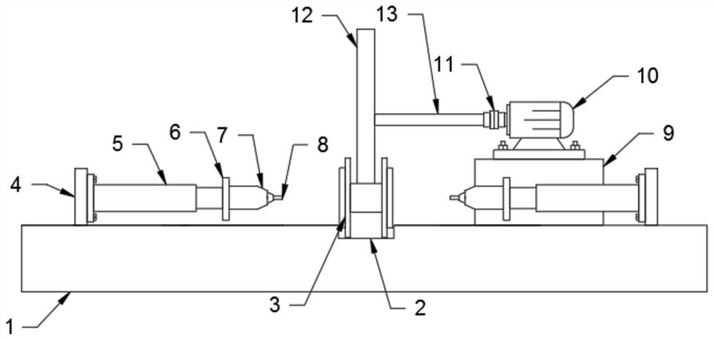
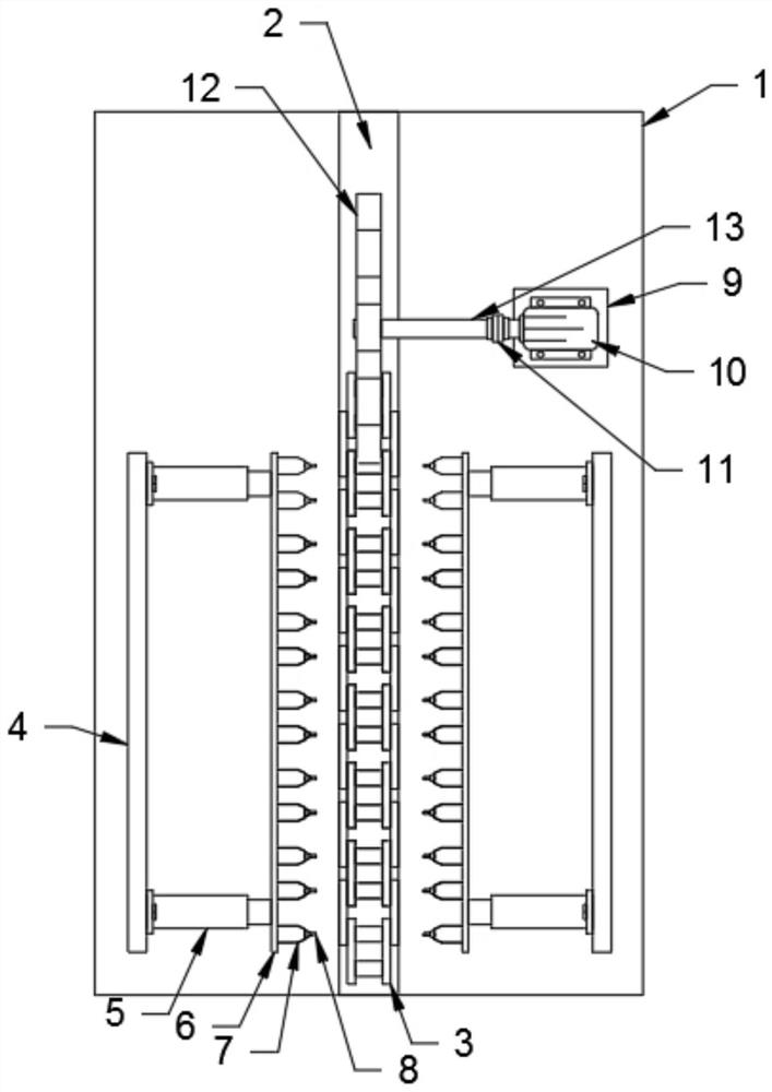
[0020] see Figure 1-3 , the present invention provides a technical solution: a hollow chain automatic riveting head device, including an operating table 1, a controller 14 is fixedly installed on the side of the operating table 1, and a plurality of fixing plates 4 are welded on the upper end of the operating table 1 to fix the The inner side of the plate 4 is fixed with several electric telescopic rods 5 by bolts, the input end of the electric telescopic rod...


PUM


Abstract

The invention discloses an automatic riveting device for a hollow chain. The automatic riveting device comprises an operation table, wherein a controller is fixedly arranged on the side edge of the operation table; a plurality of fixing plates are fixedly arranged at the upper end of the operation table; a plurality of electric telescopic rods are fixedly arranged on the inner sides of the fixing plates; connecting plates are fixedly arranged at the top ends of the electric telescopic rods; a plurality of clamps are fixedly arranged on the inner sides of the connecting plates; magnets are fixedly arranged in the clamps; riveting head nails are movably arranged at the top ends of the clamps; a fixing base is fixedly arranged on the side, away from the fixing plate, of the operation table; a motor is fixedly arranged at the upper end of the fixing base; a coupler is fixedly arranged at the left end of the motor; a connecting rod is fixedly arranged at the left end of the coupler; a chain wheel is fixedly arranged at the left end of the connecting rod; a groove is formed in the middle of the operation table; a hollow chain body is arranged in the groove in a sliding mode; and the chain wheel is connected with the hollow chain body in an engaged mode.

Description

technical field [0001] The invention relates to the technical field of automatic riveting heads, in particular to an automatic hollow chain riveting head device. Background technique [0002] The existing rivet head is an important process in the chain production process. The quality of the rivet head directly affects the firmness and service life of the chain. For hollow chains, it is extremely important. Due to the particularity of the hollow The riveting head equipment must use special equipment. At present, the commonly used riveting head equipment is a semi-automatic rocker arm riveting machine. Two workers are required to complete the work at the same time. One person is responsible for the entry and exit of the chain, and the other operates the semi-automatic rocker arm riveting machine. The equipment is a single-sided riveting head, the production efficiency is low, and it cannot meet the production schedule requirements. Moreover, due to the manual operation of the ...

Claims


Application Information

Patent Timeline
IPC IPC(8): B21L9/06
CPCB21L9/06
Inventor 姚玉明
Owner 苏州工业园区天地链条有限公司
Learn More