
Polarization multiplexing microwave photon radar detection method and system based on photon sampling

A polarization multiplexing, microwave photonic technology, applied in the field of radar detection, can solve the problems of small optical pulse repetition frequency, reduce system stability, limit the bandwidth of the received signal, etc., achieve flexible extraction, ensure coherence, and achieve frequency modulation processing Effect

Active Publication Date: 2020-08-14
ZHEJIANG LAB
View PDF7 Cites 15 Cited by
  • Summary
  • Abstract
  • Description
  • Claims
  • Application Information

AI Technical Summary

Problems solved by technology

For example, the band-pass sampling based on photon technology can realize the sampling of microwave signals by using narrow pulses with high repetition frequency, and the related technology has been used in the new radar receiving technology ([P. Ghelfi, F. Laghezza, F. Scotti, D. Onori, A. Bogoni, "Photonics for Radars Operating on Multiple Coherent Bands," Journal of Lightwave Technology , vol. 34, no. 2, pp. 500-507, 2016.]), but in the current receiving scheme based on photon bandpass sampling, the optical pulse repetition frequency is small, which limits the acceptable signal bandwidth; and the transmission and reception Separation of modules increases the complexity of the entire system and reduces the stability of the system
In addition, when processing the sampled signal, a high-speed signal processor is still required, which limits the real-time performance of the entire system.

Method used


Image

  • Polarization multiplexing microwave photon radar detection method and system based on photon sampling
  • Polarization multiplexing microwave photon radar detection method and system based on photon sampling
  • Polarization multiplexing microwave photon radar detection method and system based on photon sampling

Examples


Embodiment Construction

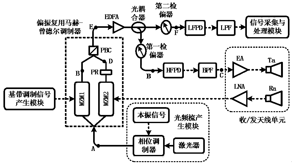
[0046] Aiming at the deficiencies of the prior art, the idea of ​​the present invention is to generate a high-frequency, tunable chirp radar transmission signal based on the photon sampling up-conversion technology, and to realize broadband echo signal reception through the photon band-pass sampling down-conversion and de-slope method. Polarization multiplexing technology realizes the above functions on a single integrated module at the same time, the system structure is simple and compact, the radar working parameters are flexible and adjustable, and the signal processing is real-time and efficient.

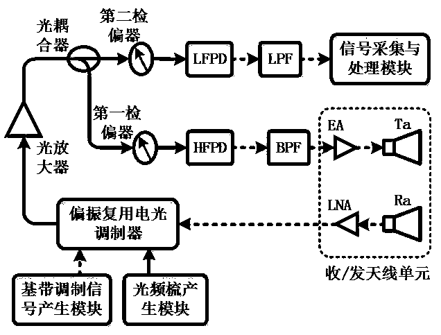
[0047] A polarization multiplexing microwave photon radar detection system based on photon sampling of the present invention, such as figure 1 As shown, it includes an optical frequency comb generation module, a baseband modulation signal generation module, a polarization multiplexing electro-optic modulator, a first polarizer, a second polarizer, and the like.

[0048] The fre...


PUM


Abstract

The invention discloses a polarization multiplexing microwave photon radar detection method and system based on photon sampling. The detection method comprises the steps that an optical frequency combsignal is divided into two paths, the baseband linear frequency modulation signal and the target echo signal respectively modulate one path of optical frequency comb signal to obtain an emission modulation optical signal and a reception modulation optical signal with orthogonal polarization states; the emission modulation optical signal and the reception modulation optical signal are combined into one path of polarization multiplexing optical signal and then are divided into two paths; two paths of signals are respectively analyzed to obtain an emission modulation optical signal and a composite optical signal containing the emission modulation optical signal and the reception modulation optical signal, the composite optical signal is subjected to photoelectric conversion and low-pass filtering to obtain an intermediate frequency signal, and the intermediate frequency signal is processed to obtain detection target information. Through a photon sampling technology and a photon polarization multiplexing technology, broadband and frequency band adjustable radar signals are generated and received, and a radar system is compact and simple and can be integrated.

Description

technical field [0001] The invention relates to a radar detection method, in particular to a microwave photon radar detection method and system using polarization multiplexing technology of photon sampling. Background technique [0002] With the development of emerging radar technology and the urgent need for new situational awareness, radar is developing in the direction of high-frequency, broadband, high-precision, real-time, multi-functional full-spectrum detection. In order to cover different spectrum spaces, the radar working band needs to be flexible and adjustable, and the signals can be processed and analyzed in real time. Limited by the bottleneck of current electronic broadband signal generation and processing technology, when functions such as signal generation, sampling, and processing are directly implemented in the microwave domain, the frequency and bandwidth are low, and the amplitude / phase response of the frequency mixing link is nonlinear. effect, and the ...

Claims


Application Information

Patent Timeline
Patent Type & Authority Applications(China)
IPC IPC(8): G01S17/42G01S17/58
CPCG01S17/42G01S17/58
Inventor 郭清水陈佳佳
Owner ZHEJIANG LAB
Learn More