
Brightness temperature inversion imaging method for uniform circular array synthetic aperture radiometer

A technology of uniform circular array and comprehensive aperture, which can be applied in the direction of using re-radiation, reflection/re-radiation of radio waves, measuring devices, etc., which can solve the problems of shortening inversion calculation time, large brightness temperature inversion error, and complex calculation process. , to achieve the effect of improving the imaging performance of brightness temperature inversion, high inversion accuracy, simple and reliable calculation

Active Publication Date: 2020-08-14
10TH RES INST OF CETC
View PDF15 Cites 3 Cited by
  • Summary
  • Abstract
  • Description
  • Claims
  • Application Information

AI Technical Summary

Problems solved by technology

[0008] The present invention aims at the problems of the UCSAIR brightness temperature inversion algorithm in the above-mentioned prior art, such as complicated calculation process, long time, large brightness temperature inversion error, etc., and provides a method with high inversion accuracy, simple and reliable calculation, and can shorten the inversion calculation. Time-based uniform circular array synthetic aperture radiometer brightness temperature retrieval imaging method

Method used


Image

  • Brightness temperature inversion imaging method for uniform circular array synthetic aperture radiometer
  • Brightness temperature inversion imaging method for uniform circular array synthetic aperture radiometer
  • Brightness temperature inversion imaging method for uniform circular array synthetic aperture radiometer

Examples


Embodiment Construction

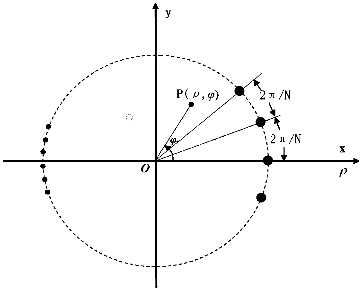
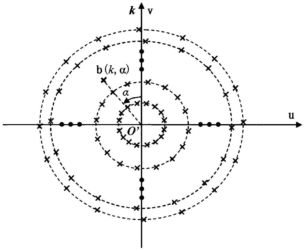
[0022] refer to figure 1 , figure 2 . According to the present invention, in the plane of the antenna array of the UCSAIR system, the center of the circular array is taken as the pole, and the ray starting from the point O and passing through the phase center of an antenna unit is the polar axis to establish a space polar coordinate system. In the two-dimensional spectral domain plane, the 0 baseline point is taken as the spectral domain origin O’, and the ray starting from O’ point in the direction vertical to the polar axis of the spectral domain is the spectral domain polar axis, and the spectral domain polar coordinate system is established. In the polar coordinate system, according to the uniform circular array synthetic aperture radiometer antenna array arrangement, the visibility function signal model of the uniform circular array synthetic aperture radiometer is established; in the visibility function signal model, the UCSAIR baseline is distributed in the spectral d...


PUM


Abstract

The invention discloses a brightness temperature inversion imaging method for a uniform circular array synthetic aperture radiometer, and aims to provide a UCSAIR brightness temperature inversion imaging method which is high in inversion precision and capable of shortening inversion calculation time. According to the technical scheme, the method comprises: under the condition of establishing a spectral domain polar coordinate system, arranging corresponding visibility functions into a visibility function matrix form by taking UCSAIR baseline spectral domain polar diameters from small to largeas a row sequence and baseline spectral domain polar angles from small to large as a column sequence; carrying out one-dimensional transverse interpolation and transverse FFT; carrying out one-dimensional longitudinal interpolation; calculating a numerical value corresponding to a fast Hankel transformation lattice point; carrying out longitudinal Hankel transformation, then carrying out transverse one-dimensional inverse Fourier transformation, and carrying out brightness temperature calibration on the transformed matrix to obtain brightness temperature distribution matrixes of each point inan observation space under the spatial polar coordinate; and displaying a brightness temperature image according to a corresponding relationship between a brightness temperature distribution matrix element position and a spatial direction to realize brightness temperature inversion imaging.

Description

technical field [0001] The invention relates to a synthetic aperture radiometer (SyntheticalApertureInterferentialRadiometer, SAIR) brightness temperature inversion imaging algorithm. Background technique [0002] The Synthetic Aperture Microwave Radiometer (SAIR) technology originates from the idea of ​​"aperture synthesis" in radio astronomy. Multiple small-aperture antennas are synthesized into an equivalent large-aperture antenna, which can effectively solve the limited aperture and mechanical scanning difficulties of traditional microwave radiometer antennas. and other issues, improving the spatial resolution. The synthetic aperture radiometer is a radiometer system that uses a sparse antenna array. It uses a correlation receiver to measure the spatial frequency domain component of the observation scene—the visibility function, and then uses an inversion algorithm to invert the observation function based on the measured visibility function. The radiation brightness tem...

Claims


Application Information

Patent Timeline
IPC IPC(8): G01S13/90
CPCG01S13/904G01S13/9011
Inventor 黄建裴乃昌熊阳
Owner 10TH RES INST OF CETC
Learn More