
Open-circuit fault detection method of three-phase inverter power tube

A three-phase inverter, open-circuit fault technology, applied in the fault location, instrument, measuring electricity and other directions, can solve the problems of high diagnosis cost, affect the diagnosis result, misdiagnosis, etc., achieve accurate fault diagnosis function, reduce fault diagnosis cost , The effect of improving work reliability

Inactive Publication Date: 2020-08-14
JIANGSU UNIV
View PDF12 Cites 8 Cited by
  • Summary
  • Abstract
  • Description
  • Claims
  • Application Information

AI Technical Summary

Problems solved by technology

For example: Chinese Patent Publication No. CN 109032011 A proposes a multi-level inverter open-circuit fault diagnosis method based on the phase voltage histogram. In the case of an open circuit fault, the voltage waveform of the three phase voltages within one cycle, and then obtain the histogram of each phase voltage, and determine the occurrence of current problems in the current circuit by comparing and analyzing the fault diagnosis characteristic value and the health status reference value when the actual circuit is working. Open-circuit fault devices, but in the actual implementation process, due to the dynamic operation of the motor and the continuous change of the current frequency, it is difficult to obtain the fault diagnosis characteristic value and the total number of sampling points in the waveform diagram within one cycle, and the degree of certainty is not high.
Another example is the Chinese Patent Publication No. CN 108303611 A, which proposes an inverter open-circuit fault diagnosis method based on the voltage rise and voltage drop of the line voltage, which first analyzes the possible values ​​of the line voltage under normal and fault conditions , according to the same probability of occurrence of positive and negative values ​​of the line voltage under normal working conditions, it is pushed to obtain each fault and the fault characteristic relationship table corresponding to the two line voltages, and the current characteristic information of the inverter’s line voltage is collected and analyzed to determine the current The fault location information of the inverter, but because the change of the load will cause the fluctuation of the line voltage, the number of positive rising edges and negative falling edges will also change, so that the special diagnosis value of the fault diagnosis will change and affect the diagnosis result. And in theory, if the carrier frequency is very small, the modulated waveform will become irregular, which will also lead to misdiagnosis in this method
Another example: Miao Beibei, Shen Yanxia and others proposed an inverter power tube open circuit fault diagnosis in the paper "Switch Tube Open Circuit Fault Diagnosis of NPC Three-Level Inverter" published in "Journal of Power Supply" 2019 Issue 05 method, which selects the switch state, the polarity of the load phase current and the phase voltage of the bridge arm as the fault characteristics, and analyzes the characteristics of the open circuit fault under different current flow paths to realize the accurate location of the fault power tube, but this method needs to select the fault There are many types of features, the cost of diagnosis in actual implementation is high, and the diagnosis system is relatively complicated

Method used


Image

  • Open-circuit fault detection method of three-phase inverter power tube
  • Open-circuit fault detection method of three-phase inverter power tube
  • Open-circuit fault detection method of three-phase inverter power tube

Examples


Embodiment Construction

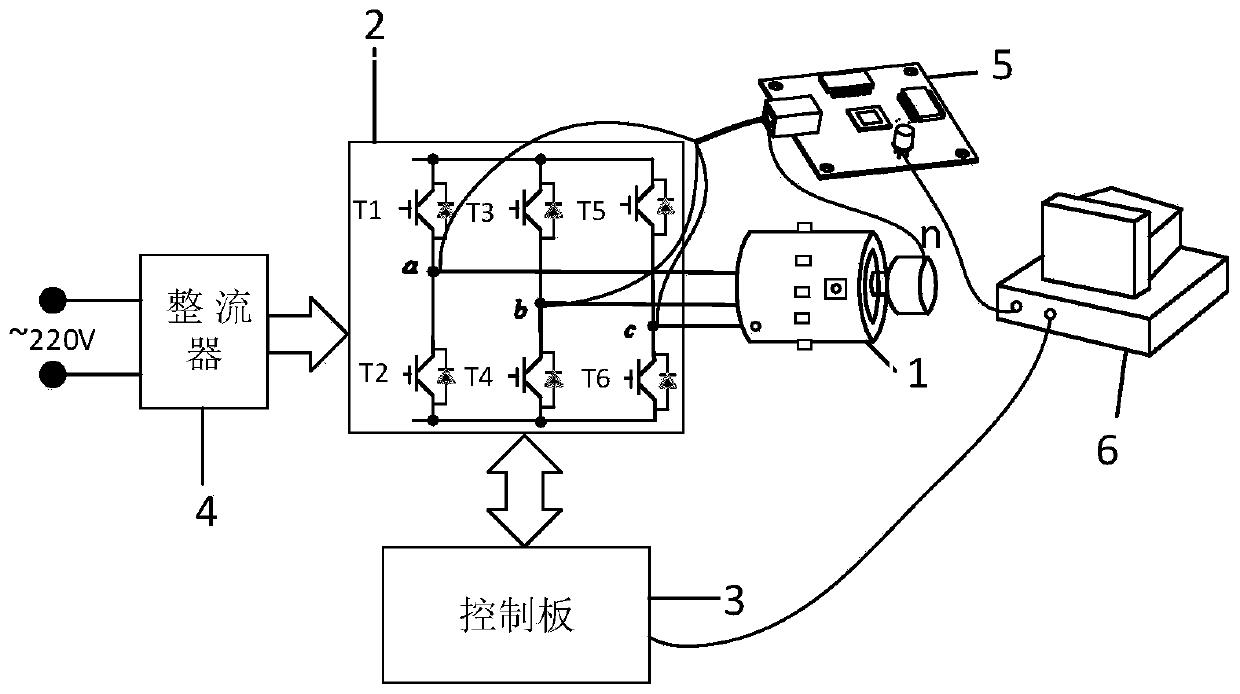
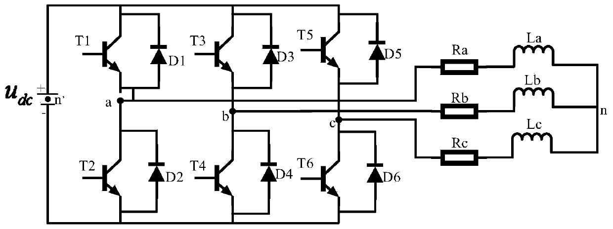
[0025] see figure 1 A detection device for implementing a method for detecting an open circuit fault of a three-phase inverter power tube according to the present invention includes a control board 3 , a rectifier 4 , a phase voltage acquisition board 5 and a host computer 6 . The rectifier 4 rectifies the 220V AC power and then inputs it into the three-phase inverter 2 in the motor drive system to convert the 220V AC power into 100V DC power u dc Used to drive the inverse three-phase converter 2. The control board 3 and the upper computer 6 are bidirectionally connected to realize mutual communication, and perform relevant algorithm processing of motor driving. The control board 3 is also bidirectionally connected with the three-phase inverter 2, the output end of the three-phase inverter 2 is connected to the permanent magnet synchronous motor 1, and the switching tube control signal sent by the control board 3 is used to drive the permanent magnet synchronous motor 1. Lea...


PUM


Abstract

The invention discloses an open-circuit fault detection method of a three-phase inverter power tube in the field of motor-driven dynamic system fault detection. Phase voltages of a three-phase inverter during normal and fault operation are acquired in a permanent magnet synchronous motor for experiments; phase voltage data under normal and fault conditions are obtained; six fault state functions are constructed; a fault state function of a to-be-tested motor is solved by using the same method; zero values and non-zero values in six sectors which are correspondingly divided are listed in each fault state function; and finally, the state values in the six sectors in the fault state functions of the to-be-detected motor are determined, if the state values are all non-zero values, the three-phase inverter has no fault, the fault state function of the to-be-detected motor is compared with the six fault state functions one by one in sequence, and if the state values are correspondingly equal, an open-circuit fault is detected to occur in the corresponding tube. According to the method, the phase voltages under the normal working condition and the fault working condition serve as fault diagnosis characteristic values, and good robustness and high accuracy are achieved.

Description

technical field [0001] The invention relates to the field of fault detection of a drive system driven by a motor, in particular to a method for detecting an open circuit fault of a power device in a three-phase voltage source inverter in a motor drive system. Background technique [0002] The motor drive system is an important part of the speed control system, and its reliability is crucial to the safe operation of the speed control system. Due to the fragility of power electronics and the complexity of their control, the inverter is a relatively fault-prone part of the motor drive system. Inverter faults in motor drive systems are mainly divided into short-circuit faults and open-circuit faults. Compared with short-circuit faults, open-circuit faults are more hidden and easier to ignore. Therefore, current research mainly focuses on open-circuit faults of inverter power tubes. . Such as: Chinese Patent Publication No. CN 109032011 A proposes a multi-level inverter open-ci...

Claims


Application Information

Patent Timeline
IPC IPC(8): G01R31/54G01R31/08G01R19/165
CPCG01R31/54G01R31/088G01R19/165
Inventor 张荣标何衍张业成
Owner JIANGSU UNIV
Learn More