Drilling position positioning system and method of drilling machine

A drilling position and positioning system technology, applied in measuring devices, directional drilling, active optical measuring devices, etc., can solve the problems of high experience and skill requirements, unfavorable drilling efficiency, long positioning time, etc., and achieve simple overall structure and saving The effect of positioning time and easy operation

Active Publication Date: 2020-08-14
63653 FORCES PLA
View PDF6 Cites 5 Cited by
  • Summary
  • Abstract
  • Description
  • Claims
  • Application Information

AI Technical Summary

Problems solved by technology

However, whether the central axis of the existing drill pipe points to the target point and whether the positioning laser beam is aligned with the center line of the rear end of the boom of the drilling rig is usually judged by the human eye, and there is a large error. The initial estimate of the average position error is about tens mm, the angular error is not less than 0.05°, the comprehensive positioning error is too large
In addition, this positioning method requires good coordination between the drilling rig operator and the target targeting personnel, requires high experience and skills of personnel, and takes a long time for positioning, which is not conducive to the improvement of drilling efficiency

Method used


Image

  • Drilling position positioning system and method of drilling machine
  • Drilling position positioning system and method of drilling machine
  • Drilling position positioning system and method of drilling machine

Examples


Embodiment Construction

[0054] The present invention will be further described below in conjunction with the accompanying drawings and specific embodiments.

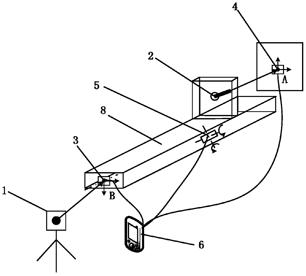
[0055] Such as figure 2 As shown, the drilling rig drilling position positioning system of this embodiment includes a positioning laser unit 1, a centering laser unit 2, a first laser position detection unit 3, a second laser position detection unit 4, an inclination detection unit 5 and a display unit 6 ;

[0056] Positioning the laser unit 1 is used to determine that the opening point A is on the working surface ( figure 2 The position on the square frame where point A is located in), and for launching the positioning laser beam to the rear end face of the boom 8 of the drilling machine;

[0057] The first laser position detection unit 3 is installed on the rear end surface of the boom 8 of the drilling rig, and is used to detect the position of the spot of the laser beam on the rear end surface;

[0058] The centering laser unit 2 is in...


PUM


Abstract

The invention discloses a drilling position positioning system and method of a drilling machine. The system comprises a positioning laser unit, a centering laser unit, a first laser position detectionunit, a second laser position detection unit, an inclination angle detection unit and a display unit. The positioning laser unit is used for determining the position of a tapping point on a working surface and emitting a positioning laser beam to the rear end surface of a big arm; the first laser position detection unit is installed on the rear end face and used for detecting the position of a light spot of a positioning laser beam on the rear end face. The centering laser unit is arranged on the big arm and is used for emitting a centering laser beam to a tapping point; the second laser position detection unit is installed on the working face and used for detecting the position of a light spot of the centering laser beam on the working face. The inclination angle detection unit is mounted on the big arm and used for detecting an inclination angle value of the big arm; the display unit is connected with each unit and is used for displaying the positioning information. The drilling position positioning system and method have the advantages of simple structure, high positioning precision, high automation level, high positioning efficiency and the like.

Description

technical field [0001] The invention mainly relates to the technical field of drilling rigs, in particular to a drilling rig drilling position positioning system and positioning method. Background technique [0002] Deep hole drilling rigs are mainly used for various types of anchoring and support operations. The positioning accuracy and positioning speed of the drilling position are directly related to the quality and efficiency of drilling. In the process of determining the initial hole position of the deep hole drilling rig, the positioning error mainly includes translation and rotation errors in the horizontal and vertical directions. Among them, the translation error mainly affects the hole opening position accuracy, and the rotation angle error mainly affects the hole deflection rate, such as figure 1 shown. [0003] figure 1 In, Δy e Expressed as the translation error in the horizontal direction; Δz e Expressed as the translation error in the vertical direction; ...

Claims


Application Information

Patent Timeline
Patent Type & Authority Applications(China)
IPC IPC(8): G01C15/00E21B7/04
CPCG01C15/002E21B7/04
Inventor 不公告发明人
Owner 63653 FORCES PLA
Why Eureka
Try Eureka