A caliper encircling coil erecting device

A coil and caliper technology, which is applied in hoisting devices, hoisting devices, coil manufacturing, etc., can solve problems such as potential safety hazards, high energy consumption, and increased coil potential energy, and achieve an effective and controllable turning process

Active Publication Date: 2021-05-07
江西变电设备有限公司
View PDF5 Cites 0 Cited by
  • Summary
  • Abstract
  • Description
  • Claims
  • Application Information

AI Technical Summary

Problems solved by technology

This kind of movement combination undoubtedly increases the potential energy of the coil, and there is a safety hazard in the process of standing up, and more energy consumption needs to be paid

Method used


Image

  • A caliper encircling coil erecting device
  • A caliper encircling coil erecting device
  • A caliper encircling coil erecting device

Examples


Embodiment Construction

[0020] In order to facilitate the understanding of the present invention, the present invention will be described more fully below with reference to the associated drawings. A preferred embodiment of the invention is shown in the drawings. However, the present invention can be embodied in many different forms and is not limited to the embodiments described herein. Rather, these embodiments are provided so that the disclosure of the present invention will be thorough and complete.

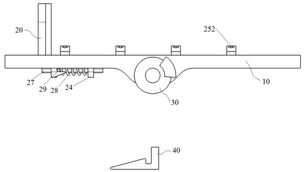
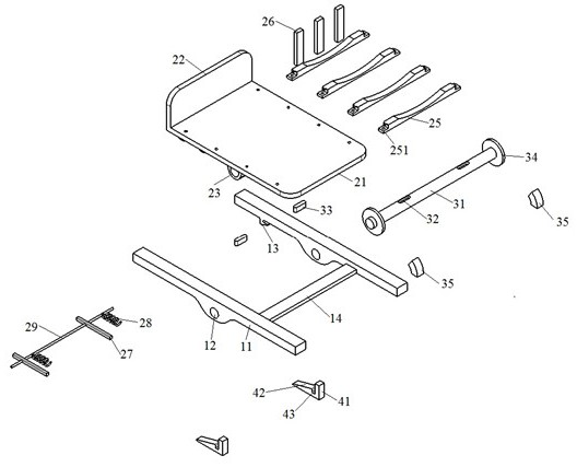
[0021] see Figure 1-Figure 4 The caliper encircling type coil erecting device shown includes a supporting part 10, an overturning part 20, a braking part 30 and a limiting part 40. The supporting part 10 is installed on the ground, and a pothole is reserved on the ground below the supporting part 10 for the overturning part. The overturning of 20 provides space, the overturning part 20 is installed on the supporting part 10, the brake part 30 connects the overturning part 30 and the supporting pa...


PUM


Abstract

A caliper embracing type coil erecting device, which belongs to the technical field of transformer production, includes a supporting part, a turning part, a braking part and a limiting part. The supporting part is installed on the ground, and a hole is reserved on the ground below the supporting part. On the supporting part, the braking part is connected to the turning part and the supporting part, and the limiting part is installed in the pit below the supporting part. The supporting part includes a beam, a shaft hole, an upper limit boss and a baffle. The beams are a pair. The pair of beams are installed on the ground. It has an upper limit boss, and the upper limit boss has an inclined platform and a groove. The turning part includes a horizontal plate, a vertical plate, a rotating lug, a limit lug, a square slider, a spring and a limit rod. The horizontal plate and the vertical plate form a mutually perpendicular turning plate, and the finished coil is placed on the turning plate. There is a pair of rotating lugs at the bottom of the horizontal plate, and the position of the rotating lugs corresponds to the position of the shaft hole.

Description

technical field [0001] The invention belongs to the technical field of transformer production, in particular to a caliper-embracing coil erecting device. Background technique [0002] After the winding of the transformer coil is completed, it is generally necessary to change it from a lying position to a standing position. At this time, a special coil erecting device is required. At present, each transformer manufacturer has its own coil erecting device, which is usually relatively simple. Other power sources turn the coils from prone to standing. These devices typically drive one end of the coil in a prone position upwards, and the other end adapts until the coil changes to an upright position. This combination of motions undoubtedly increases the potential energy of the coil, which poses a safety hazard during the stand-up operation, and more energy consumption needs to be paid. Contents of the invention [0003] The present invention provides a caliper encircling type...

Claims


Application Information

Patent Timeline
Patent Type & Authority Patents(China)
IPC IPC(8): B66F19/00H01F41/04
CPCB66F19/00H01F41/04
Inventor 杨国新王玮
Owner 江西变电设备有限公司
Why Eureka
Try Eureka