
Demolding structure of injection mold

A technology of injection molds and injection molds, which is applied in the field of molds, can solve problems such as damage to injection molded parts, and achieve the effects of reducing defective rate, gravitational potential energy, and loss

Inactive Publication Date: 2020-08-14
吉安集睿科技有限公司
View PDF11 Cites 2 Cited by
  • Summary
  • Abstract
  • Description
  • Claims
  • Application Information

AI Technical Summary

Problems solved by technology

[0003] However, in the prior art, in the process of ejecting and separating the injection molded parts, the ejected injection molded parts in the vertically arranged mold fall from a height, and the injection molded parts of different heights gradually fall to the collection area, which has a certain When the injection molded parts with gravitational potential energy fall to the collection area, there will be collisions between the injection molded parts that have fallen successively, causing damage to the injection molded parts and increasing the defective rate

Method used


Image

  • Demolding structure of injection mold
  • Demolding structure of injection mold
  • Demolding structure of injection mold

Examples


Embodiment Construction

[0032] The following will clearly and completely describe the technical solutions in the embodiments of the present invention with reference to the accompanying drawings in the embodiments of the present invention. Obviously, the described embodiments are only some, not all, embodiments of the present invention. Based on the embodiments of the present invention, all other embodiments obtained by persons of ordinary skill in the art without creative efforts fall within the protection scope of the present invention.

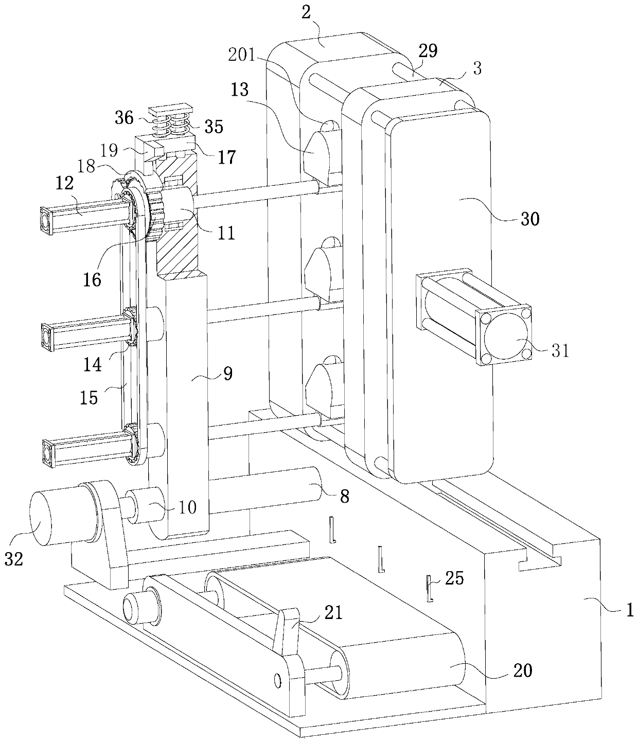
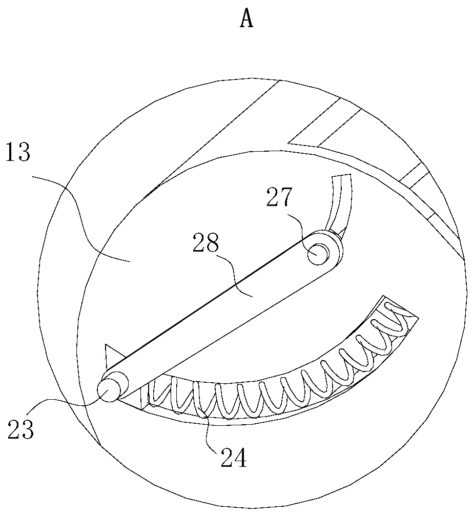
[0033] see Figure 1-9 , the present invention provides a technical solution: a demoulding structure of an injection mold, including a base 1, a fixed mold 3 fixedly connected to the rear side of the top of the injection mold base, and three rows of injection grooves 201 arranged in an array on the front of the fixed mold 3 , the side of the fixed mold 3 is connected with the injection pipe connected with the injection groove 201, the top of the base 1 is located i...


PUM


Abstract

The invention discloses a demolding structure of an injection mold, and belongs to the technical field of molds. The demolding structure of the injection mold comprises a base, a fixed mold is fixedlyconnected to the rear side of the top of an injection mold base, three rows of injection molding grooves distributed in an array mode are formed in the front face of the fixed mold, the side face ofthe fixed mold communicates with an injection pipe communicating with the injection molding grooves, a movable mold is slidably connected to the position, located in front of the fixed mold, of the top of the base, the fixed mold and the movable mold are connected through a mold closing unit, an ejection unit for ejecting an injection molding part is connected to the back face of the fixed mold, and a material receiving unit is connected to the rear end of the side face of the base. By arranging a supporting shaft, a mounting plate, a driving shaft, a mounting shaft, a second electric cylinder, a receiving hopper, a linkage gear, a transmission belt, a follow-up gear, an L-shaped plate, an arc-shaped toothed plate, a trapezoidal block and a conveying belt, the problem that the injection molding part falls down from a high position and collides with the injection molding part in a collecting area, and consequently the injection molding part is damaged is solved, and the defective rate of the injection molding part is reduced.

Description

technical field [0001] The invention relates to the technical field of molds, in particular to a demoulding structure of an injection mold. Background technique [0002] Injection mold is a tool for producing plastic products; it is also a tool for giving plastic products complete structure and precise dimensions. In the prior art, most injection molds include a fixed mold and a movable mold, and parts of the injection mold need to be separated in an orderly manner so as to eject the injection molded part. [0003] However, in the prior art, in the process of ejecting and separating the injection molded parts, the ejected injection molded parts in the vertically arranged mold fall from a height, and the injection molded parts of different heights gradually fall to the collection area, which has a certain When the injection molded parts with gravitational potential energy fall to the collection area, collisions will occur between the successively falling injection molded par...

Claims


Application Information

Patent Timeline
Patent Type & Authority Applications(China)
IPC IPC(8): B29C45/40B29C45/17
CPCB29C45/1769B29C45/1771B29C45/4005
Inventor 罗层
Owner 吉安集睿科技有限公司
Learn More