Condensation treatment method and device for removing siloxane components in biomass gas

A treatment method and technology for siloxane, applied in separation methods, chemical instruments and methods, dispersion particle separation, etc., can solve the problems of poor siloxane treatment and high cost, and achieve the effect of improving efficiency and reducing cost

Inactive Publication Date: 2020-08-14
NANJING CARBON RECYCLE BIOMASS ENERGY CO LTD
View PDF8 Cites 0 Cited by
  • Summary
  • Abstract
  • Description
  • Claims
  • Application Information

AI Technical Summary

Problems solved by technology

[0005] The purpose of the present invention is to solve the problem of poor siloxane treatment and high cost in biomass gas, and to invent a method to condense and precipitate siloxane components at a lower temperature by lowering the gas temperature, so as to achieve the purpose of removal Condensation treatment method and device for removing siloxane components in biomass gas

Method used


Image

  • Condensation treatment method and device for removing siloxane components in biomass gas
  • Condensation treatment method and device for removing siloxane components in biomass gas

Examples


Embodiment 1

[0026] Such as Figure 1-2 shown.

[0027] A condensation treatment method for removing siloxane components in biomass gas, comprising the following steps:

[0028] First, set up a heat exchanger for the entry and exit of siloxane-containing biomass gas for heat recovery and pre-cooling of intake air;

[0029] Secondly, two condensers are set up, and the siloxane-containing biomass gas enters the first condenser and the second condenser in turn through the control valve, and at the same time, the first condenser and the second condenser work as the evaporator and defrost respectively. device status.

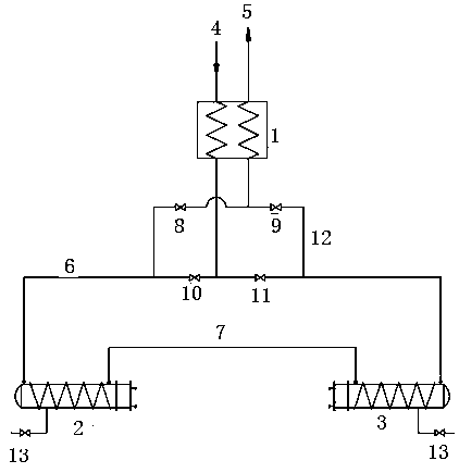
[0030] (1) if figure 1 shown. The intake air passes through the heat exchanger 1 and the outlet air for heat recovery to achieve pre-cooling of the intake air, and then through valve control, the first condenser 2 > the second condenser 3 and the second condenser 3 > the first condenser 2 Flow state for switching operation.

[0031] (2) When the first valve 8 and the fourth...

Embodiment 2

[0038] Such as Figure 1-2 shown.

[0039] A condensation treatment device for removing siloxane components in biomass gas, which includes a heat exchanger 1, a first condenser 2 and a second condenser 3, such as figure 1 shown. The heat exchanger 1 is provided with an inlet pipeline 4 and an outlet pipeline 5, and the inlet pipeline 4 communicates with the inlet ends of the first condenser 2 and the second condenser 3 through the inlet pipeline 6, and the first condenser 2 It communicates with the outlet end of the second condenser 3 through a connecting pipe 7, and a third valve 10 and a fourth valve 11 are installed on the inlet pipe 6 communicating with the first condenser 2 and the second condenser 3, and The connection point between the air pipeline 4 and the air inlet pipe 6 is located between the third valve 10 and the fourth valve 11; the air inlet pipe 6 on the outside of the third valve 10 and the fourth valve 11 is connected with a return air pipe 12 respectively...


PUM

PropertyMeasurementUnit
Thicknessaaaaaaaaaa
Apertureaaaaaaaaaa
Aperture sizeaaaaaaaaaa

Abstract

The invention discloses a condensation treatment method and device for removing siloxane components in biomass gas. The method comprises comprises the following steps that firstly, a heat exchanger allowing siloxane-containing biomass gas to enter and exit is arranged and used for conducting heat recovery to achieve inlet gas precooling, secondly, two condensers are arranged, the siloxane-containing biomass gas is made to enter a first condenser and a second condenser in turn through control valves, and meanwhile the first condenser and the second condenser are made to work outside an evaporator and a defroster respectively. The method provided by the invention has the advantages of high efficiency, strengthening, stability, reliability and continuous operation, the siloxane danger-removing effect is superior to that of any one of the existing methods, the efficiency is improved by 80% or more, the cost is reduced by 60% or more, and the method can be connected for long-term operationand can continuously work for half a year to one year or more.

Description

technical field [0001] The invention relates to a waste gas treatment method, in particular to a biomass gas treatment technology, in particular to a condensation treatment method and device for removing siloxane components in biomass gas. Background technique [0002] Siloxane in biomass gas is a kind of silicon-containing organic components. They are mainly derived from softeners in daily necessities in people's lives. When wastewater or waste containing softeners is collected in sewage treatment plants or landfills During biochemical treatment, it will be released into the generated biogas, landfill gas and other biomass gases, thus becoming a characteristic component of biomass gases. [0003] The siloxane components in biomass gas mainly include hexamethyldisiloxane, octamethylcyclotetrasiloxane, decamethylcyclopentasiloxane, dodecamethylcyclohexasiloxane, etc. These groups The total content concentration in biomass gas is generally between a few milligrams per cubic m...

Claims


Application Information

Patent Timeline
IPC IPC(8): B01D53/00
CPCB01D53/002
Inventor 王卫星王慧杨军王卫兵徐明刚刘仁刚陈泽智吴未立
Owner NANJING CARBON RECYCLE BIOMASS ENERGY CO LTD
Why Eureka
Try Eureka