Eureka AIR delivers breakthrough ideas for toughest innovation challenges, trusted by R&D personnel around the world.

Enema device capable of reducing enterobrosis probability

A technology of intestinal perforation and enema, which is applied in the direction of enema device/irrigator, puncture needle, drug equipment, etc. It can solve the problems such as difficulty in grasping the insertion force of enema tube, insufficient lubrication of intestinal inner wall, and difficulty in judging, so as to reduce and avoid Intestinal perforation phenomenon, safe and convenient perfusion process, easy to hold and control effect

Inactive Publication Date: 2020-08-14
THE FIRST AFFILIATED HOSPITAL OF ZHENGZHOU UNIV
View PDF0 Cites 7 Cited by
  • Summary
  • Abstract
  • Description
  • Claims
  • Application Information

AI Technical Summary

Problems solved by technology

[0004] In view of the above situation, in order to make up for the technical deficiencies of the existing technology, the present invention provides an enema device that can reduce the probability of intestinal perforation, so as to solve the problem of difficulty in grasping the insertion force of the enema tube in the existing enema operation, insufficient lubrication of the inner wall of the intestinal tract, The perfusion resistance is large and easy to block, and the perfusion pressure is difficult to judge, so the hidden danger of intestinal perforation cannot be eliminated in time

Method used


Image

  • Enema device capable of reducing enterobrosis probability
  • Enema device capable of reducing enterobrosis probability
  • Enema device capable of reducing enterobrosis probability

Examples


Embodiment Construction

[0011] The specific implementation manners of the present invention will be described in further detail below in conjunction with the accompanying drawings.

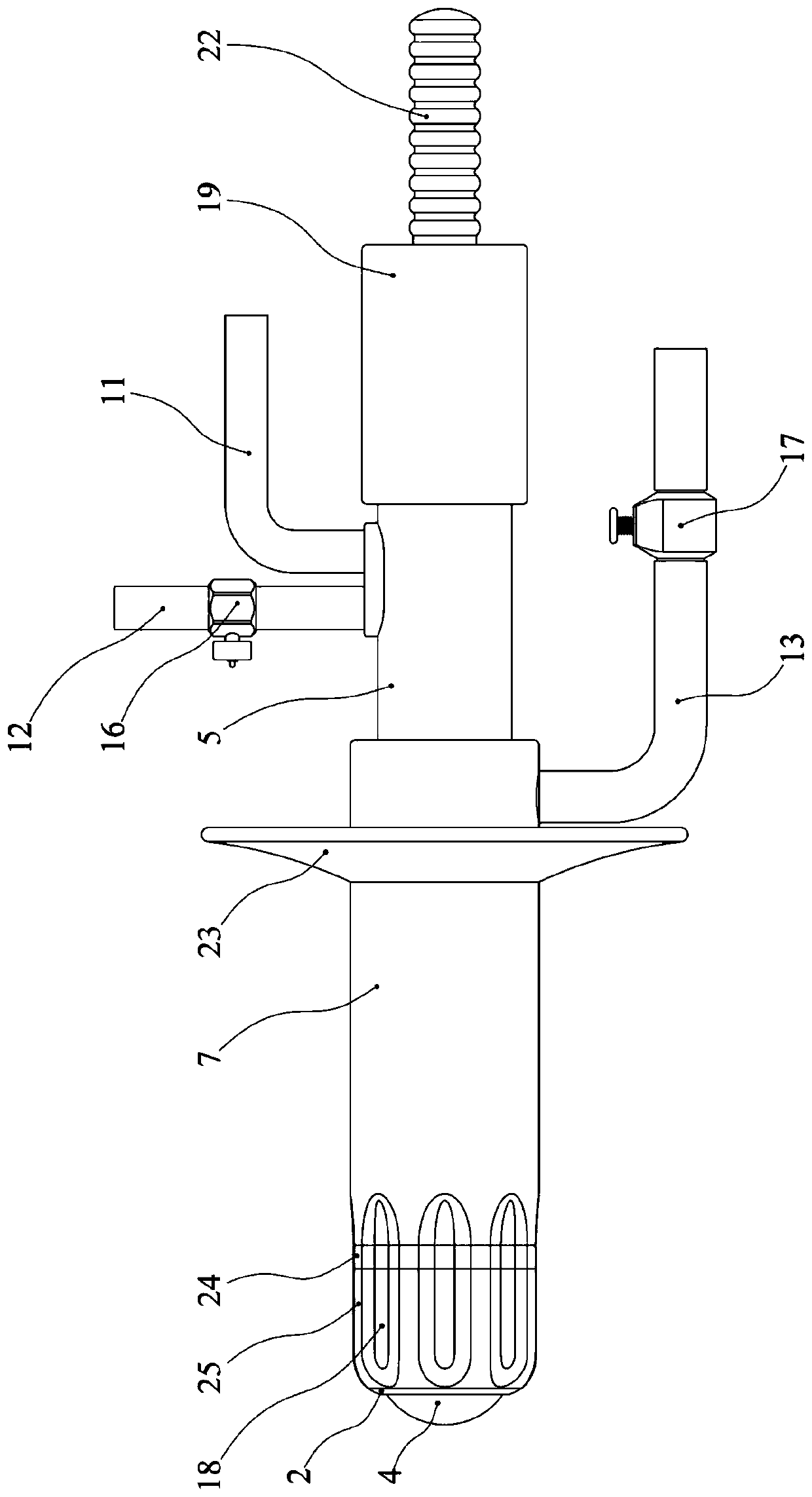
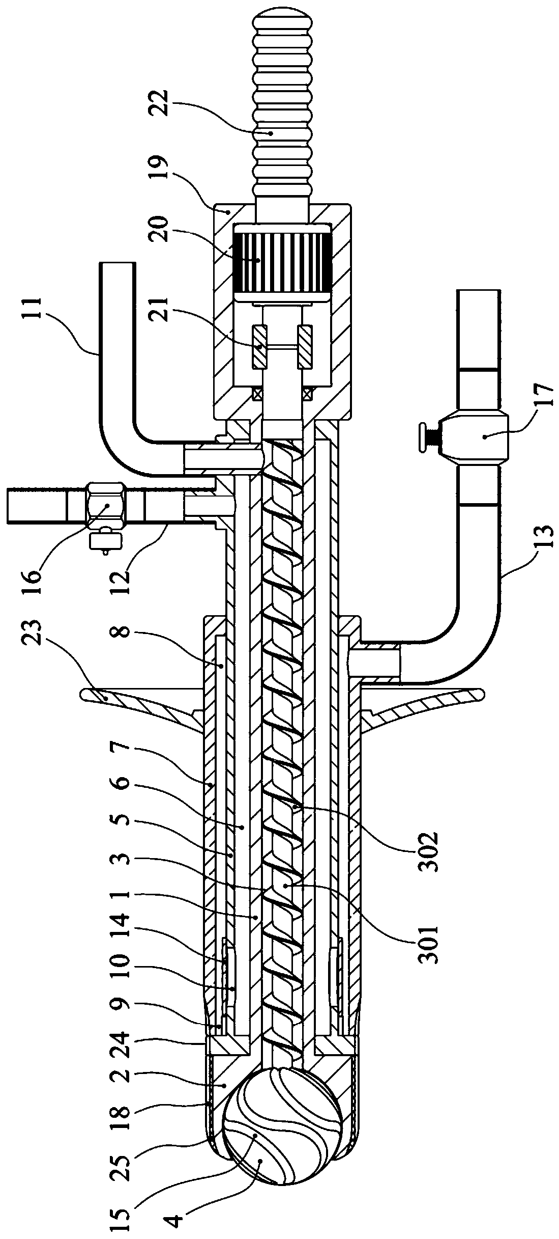
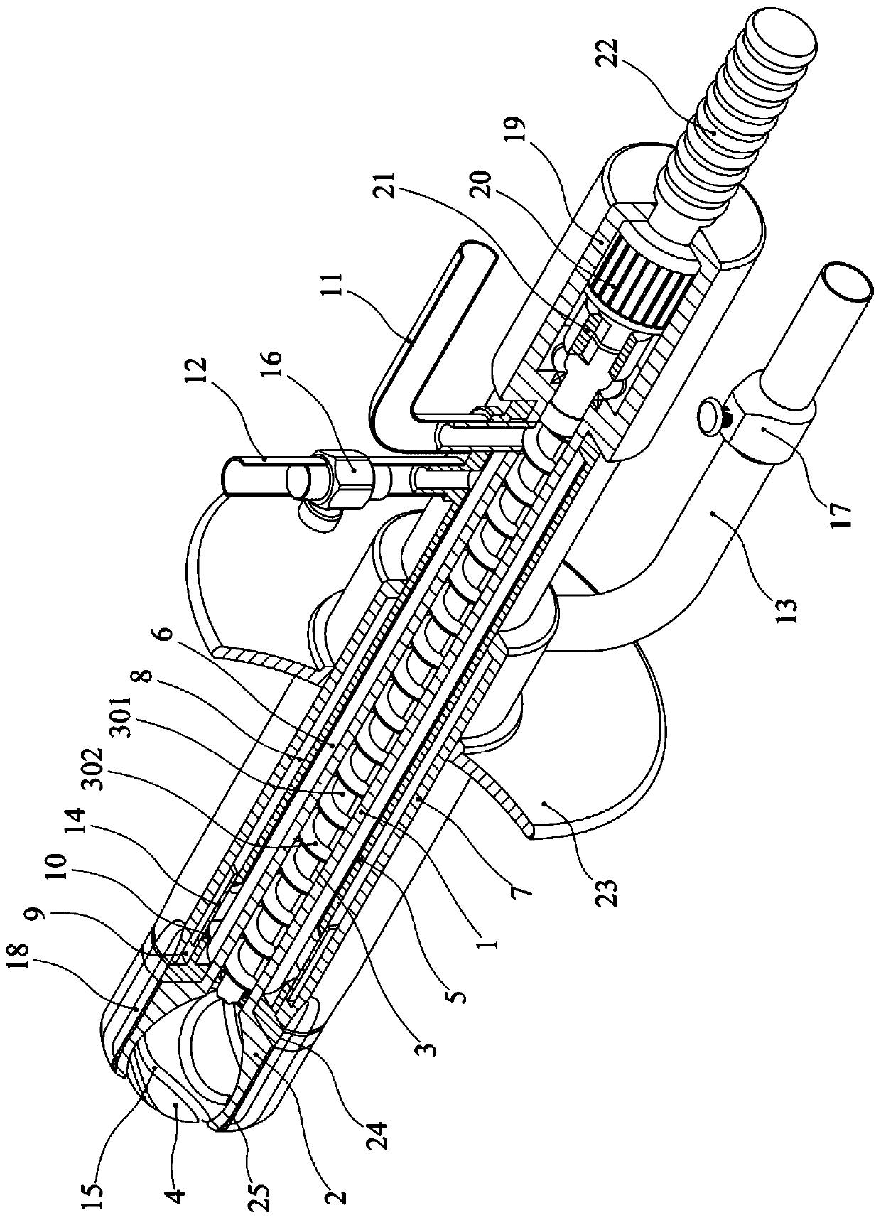
[0012] Depend on Figure 1 to Figure 4 Provided, the present invention includes a horizontally arranged hollow cannula 1, the left end of the cannula 1 has an enema head 2 with an outer diameter larger than the cannula 1 and a smooth left end, and the cannula 1 is placed on the inside of the cannula 1 and is connected to the cannula 1. The screw conveyor 3 coaxially arranged with the intubation tube 1 is composed of a rotating shaft 301 and a spiral blade 302 surrounding the rotating shaft 301. The length of the rotating shaft 301 is greater than the length of the screw blade 302. The enema head 2 has The ball 4 that is freely rotatably connected with the enema head 2, the ball center of the ball 4 is placed on the axis of the screw conveyor 3 and the ball 4 is connected to the left end of the screw conveyor 3, and a par...


PUM


Abstract

The invention relates to an enema device capable of reducing enterobrosis probability, and aims to solve the problems that a conventional enema device is difficult to control, the intestine lubrication is insufficient, the pouring resistance is large and the pouring pressure is difficult to judge and reduce. The enema device capable of reducing enterobrosis probability comprises a hollow intubatewhich is horizontally arranged, wherein an enema head is arranged at the left end of the intubate; a spiral conveyer arranged on the inner side of the intubate is arranged on the intubate; a ball applicator formed by balls which freely rotate is arranged on the enema head; the right end of the spiral conveyer is in shaft sealing connection with the right end of the intubate; a sleeve is arranged on the intubate; the left end and the right end of the sleeve are respectively in sealing connection with the intubate; a first interlayer is formed between the sleeve and the intubate; a sliding sleeve is arranged on the sleeve; the left end and the right end of the sliding sleeve are in axial sliding connection with the sleeve; a second interlayer is formed between the sliding sleeve and the sleeve; a liquid inlet hole is formed in the left end surface of the sliding sleeve; a drainage hole which communicates with the first interlayer and the second interlayer is formed in the sleeve; a liquid injecting pipe arranged on the right side of the sliding sleeve is arranged on the intubate; a liquid inlet pipe arranged on the right side of the sliding sleeve is arranged on the sleeve; and a stream back pipe which communicates with the second interlayer is arranged on the sliding sleeve.

Description

technical field [0001] The invention relates to a sausage enema device, in particular to a sausage enema device which can reduce the probability of intestinal perforation. Background technique [0002] Enema is a relatively common auxiliary medical technique in the process of disease treatment. It is used for dredging patients with constipation, cooling patients with high fever, preoperative preparation for abdominal surgery, and removing intestinal gas and harmful substances. The existing enema treatment is through enema Although this method can complete the enema treatment, it has many shortcomings: First, lubricating oil needs to be applied in advance before the enema tube is inserted, and because the enema tube is soft and the enema after smearing The tube is slippery and difficult to hold, it is difficult to control the strength and speed during insertion, and the resistance feedback during the insertion process cannot be accurately judged, which is easy to cause damage...

Claims


Application Information

Patent Timeline
IPC IPC(8): A61M3/02A61M31/00
CPCA61M3/0279A61M31/00A61M2210/1042A61M2210/1067A61M2210/005
Inventor 程波朱长举陈倩柴宇霞吴忠卫崔宗朝
Owner THE FIRST AFFILIATED HOSPITAL OF ZHENGZHOU UNIV
Why Eureka
Eureka Blog
Learn More