Driving control method and circuit of power tube

A technology for driving control circuits and power tubes, which is applied to output power conversion devices, electrical components, etc. Wide duration and other issues to achieve the effect of improving symmetry

Active Publication Date: 2020-08-11
SHENZHEN NANYUN MICROELECTRONICS CO LTD
View PDF4 Cites 0 Cited by
  • Summary
  • Abstract
  • Description
  • Claims
  • Application Information

AI Technical Summary

Problems solved by technology

In practical applications, output ripple asymmetry often occurs, which will lead to reduced efficiency of the power module and poor load regulation
[0004] The reasons for the asymmetry of the output ripple may be that the internal resistance of the power tube is inconsistent, or the parasitic capacitance is inconsistent, and the power tube does not match due to wiring and other reasons, resulting in an asymmetrical pulse width at the transformer input end of the push-pull converter. The time is long, which leads to the different charging time of the secondary output on the capacitor, resulting in asymmetrical output ripple.
[0005] For example, if the parasitic capacitance of the power tube is too large, the charging time of the gate of the power tube will be longer, so that the rise time of the gate and drain of the power tube will be longer (the rise time refers to the power tube gate / drain input Rising time from 10% to 90%); if the parasitic capacitance of the power tube is too small, it will cause the rise time of the gate and drain to be shortened
The change of rise time will affect the actual conduction time of the power tube, and then affect the output ripple

Method used


Image

  • Driving control method and circuit of power tube
  • Driving control method and circuit of power tube
  • Driving control method and circuit of power tube

Examples


Embodiment Construction

[0051] In order to make the objectives, technical solutions and advantages of the present invention clearer, the following further describes the present invention in detail with reference to the accompanying drawings and embodiments. It should be understood that the specific embodiments described here are only used to explain the present invention, but not to limit the present invention.

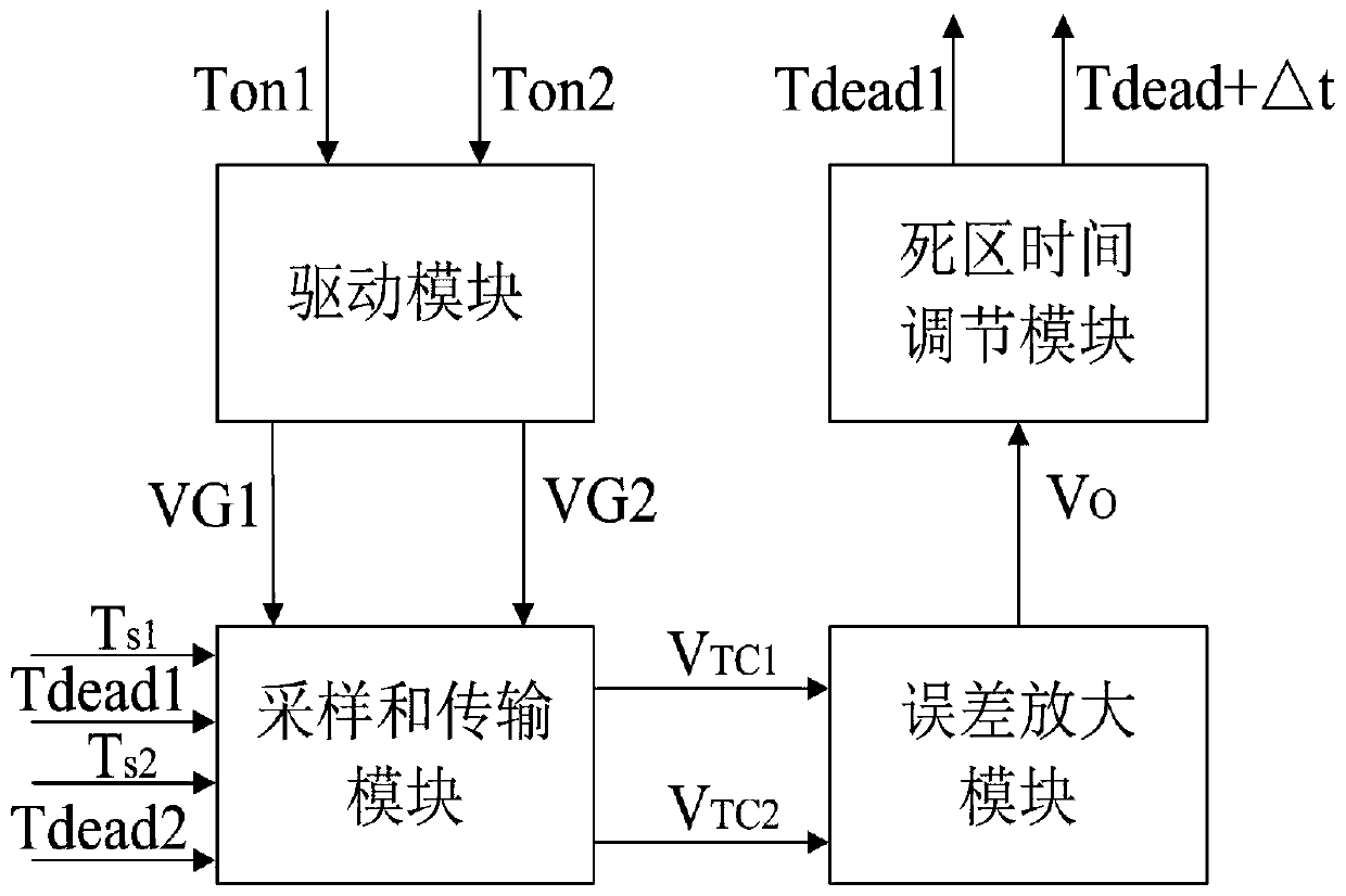
[0052] figure 1 Shown is the circuit principle block diagram of the present invention. The drive control circuit of the power tube of the present invention includes a drive module, a sampling and transmission module, an error amplification module, and a dead time adjustment module. The inventive concept of this application is to directly time-sampling the actual conduction time of the two power tubes by adopting the symmetric compensation technology to obtain the difference between the actual conduction times of the two power tubes, and adjust the conduction time by converting the conduction ti...


PUM


Abstract

The invention discloses a driving control method of a power tube, which is applied to a push-pull converter. The driving control circuit of the power tube comprises a driving module, a sampling and transmitting module, an error amplifying module and a dead time adjusting module. According to the invention, the actual conduction time of the two power tubes is directly sampled in a time-sharing manner by adopting a symmetric compensation technology to obtain the difference of the actual conduction time of the two power tubes so as to adjust the internal dead time. According to the invention, thedead time of one power tube in the next period is adjusted by converting the conduction time into the voltage, so that the actual conduction time of the two power tubes tends to be consistent, and the symmetry of output ripples is improved.

Description

Technical field [0001] The invention relates to a switch type converter, in particular to a drive control method and circuit of a power tube in a push-pull converter. Background technique [0002] Constant voltage power modules often use push-pull converter topologies, which have the advantages of simple structure, high efficiency, and small size, and are widely used. [0003] In the push-pull converter, the output ripple is an important parameter index, which will affect the efficiency and load regulation rate of the power module. In practical applications, the phenomenon of asymmetry of output ripple often occurs, which will reduce the efficiency of the power module and the load regulation rate. [0004] The reason for the asymmetry of the output ripple may be that the internal resistance of the power tube is inconsistent, or the parasitic capacitance is inconsistent, and the power tube is not matched due to wiring and other reasons, which leads to an asymmetric pulse width at the...

Claims


Application Information

Patent Timeline
IPC IPC(8): H02M1/088H02M1/38
CPCH02M1/088H02M1/38H02M1/385
Inventor 曾正球周阿铖陈树澍
Owner SHENZHEN NANYUN MICROELECTRONICS CO LTD
Why Eureka
Try Eureka