
Optical lens, camera module and assembling method thereof

An optical lens and assembly method technology, applied in the field of optical imaging, can solve the problems of different components and properties, affecting the overall performance and reliability of modules, and affecting the performance and reliability of plastic materials.

Pending Publication Date: 2020-08-11
NINGBO SUNNY OPOTECH CO LTD
View PDF0 Cites 2 Cited by
  • Summary
  • Abstract
  • Description
  • Claims
  • Application Information

AI Technical Summary

Problems solved by technology

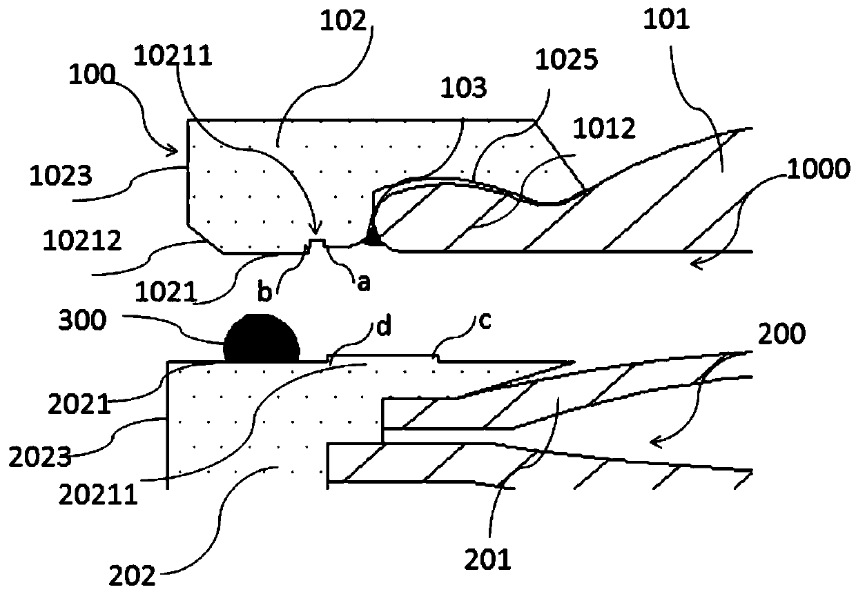
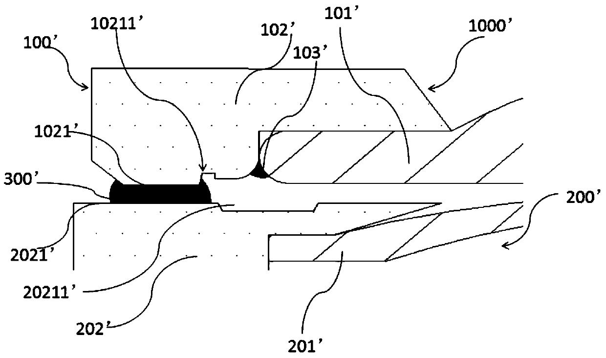
[0005] However, when assembling the above-mentioned lenses, it is necessary to use adhesive materials to bond and fix the upper and lower sub-lenses. However, the adhesive materials are in a liquid state and have fluidity when they are not cured. There is a time interval between them, so the glue material has a tendency to flow and spread to both sides in the glue painting area. Aligned with a small gap, which allows the adhesive to be squeezed and spread both inside and outside the lens
The adhesive material diffused to the outside is to affect the appearance, and the second is to overflow and affect the motor or other components, thereby affecting the overall performance and reliability of the module; the adhesive material diffused to the inside is to flow into the lens and not expected to be bonded position, which affects the performance and reliability of the lens; the second is that it is easy to touch the adhesive material between the lens barrel of the sub-lens and the lens. The composition and performance of the two adhesive materials are different, which will affect the overall performance of the two adhesive materials. reliability

Method used


Image

  • Optical lens, camera module and assembling method thereof
  • Optical lens, camera module and assembling method thereof
  • Optical lens, camera module and assembling method thereof

Examples


Embodiment Construction

[0096] For a better understanding of the application, various aspects of the application will be described in more detail with reference to the accompanying drawings. It should be understood that these detailed descriptions are descriptions of exemplary embodiments of the application only, and are not intended to limit the scope of the application in any way. Throughout the specification, the same reference numerals refer to the same elements. The expression "and / or" includes any and all combinations of one or more of the associated listed items.

[0097] It should be noted that in this specification, expressions of first, second, etc. are only used to distinguish one feature from another, and do not represent any limitation on the features. Accordingly, a first body discussed hereinafter may also be referred to as a second body without departing from the teachings of the present application.

[0098] In the drawings, the thickness, size and shape of objects have been slight...


PUM

PropertyMeasurementUnit
widthaaaaaaaaaa
depthaaaaaaaaaa
heightaaaaaaaaaa

Abstract

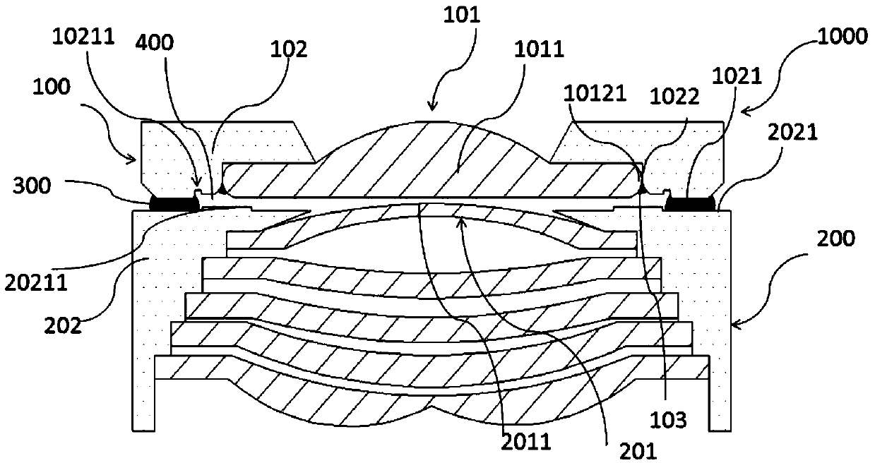
The present invention provides an optical lens. The optical lens comprises a first lens component comprising at least one first lens, a second lens component comprising at least one second lens, and afirst adhesive material, wherein the at least one second lens and the at least one first lens jointly form an imageable optical system, the first adhesive material is located in a first gap between the first lens component and the second lens component, the first adhesive material is suitable for supporting and fixing the first lens component and the second lens component after being cured, the first lens component is provided with a first bottom surface, the second lens component is provided with a second top surface, and the first bottom surface and / or the second top surface are / is providedwith a glue drawing area for arranging the first adhesive material, the first bottom surface is provided with a first adhesive blocking part, and / or the second top surface is provided with a third adhesive blocking part. The invention further provides a corresponding camera module and an assembling method of the optical lens. The optical lens is advantaged in that influence of the first adhesivematerial on the optical lens can be prevented, and the imaging quality of the optical lens or the camera module can be improved.

Description

technical field [0001] The invention relates to the technical field of optical imaging, in particular, the invention relates to an optical lens, a camera module and an assembly method of the optical lens. Background technique [0002] With the popularization of mobile electronic devices, related technologies of camera modules used in mobile electronic devices to help users acquire images (such as video or images) have developed rapidly and improved rapidly, and in recent years, camera modules Groups have been widely used in many fields such as medical treatment, security, industrial production and so on. [0003] In the process of improving the imaging capability of the camera module, there are three main factors affecting the imaging quality: one is the imaging quality of the lens, and a high-quality lens can well correct the aberration of the optical system to achieve higher imaging quality; It is the light-sensing ability of the photosensitive chip. Generally speaking, t...

Claims


Application Information

Patent Timeline
Patent Type & Authority Applications(China)
IPC IPC(8): G02B7/02
CPCG02B7/025
Inventor 陈烈烽梅哲文田中武彦孙鑫翔刘林
Owner NINGBO SUNNY OPOTECH CO LTD
Learn More