
Optical fiber probe combining OCT imaging and pressure sensing and method thereof

A fiber optic probe and pressure technology, applied in sensors, medical science, measuring devices, etc., can solve the problems of large volume, difficult preparation, and high requirements, and achieve the effects of optimizing the probe structure, improving experimental efficiency, and reducing the size of the probe

Pending Publication Date: 2020-08-11
SUN YAT SEN UNIV
View PDF0 Cites 0 Cited by
  • Summary
  • Abstract
  • Description
  • Claims
  • Application Information

AI Technical Summary

Problems solved by technology

[0002] There are the following problems in the existing methods: 1. In the experiment, the optical fiber probe cannot simultaneously obtain the pressure value information and the cross-sectional depth image information of the object to be measured. For example, when detecting vascular sclerosis, it is necessary to know the blockage depth. Statistics on blood flow velocity and pulse information are also needed to further determine the extent of vascular sclerosis and the impact of vascular sclerosis on blood flow
2. Most of the pressure measuring probes used today are metal probes, which are large in size and high in cost, and are not suitable for detection in animal organisms
3. The preparation of most pressure measuring probes is too complicated, and the film collection and adhesion process needs to be operated under a microscope. The requirements for the operating environment and experimental materials are high, and it is generally not easy to prepare
4. General pressure measuring probes are not suitable for the detection of some special objects to be measured, which are easy to conduct and pollute, and are susceptible to electromagnetic interference.

Method used


Image

  • Optical fiber probe combining OCT imaging and pressure sensing and method thereof

Examples


Embodiment 2

[0045] Embodiment 2 (pressure detection)

[0046] The principle of diaphragm pressure sensing is to use the interference principle of light. When the light emitted by the laser passes through the optical fiber and reaches the FP cavity to generate reflected light, the finally reflected light passes through the optical fiber back to the coupler and interferes with the system to obtain the optical path difference. Then according to The deformation and pressure values ​​determine the sensor sensitivity. When the FP cavity is deformed by external pressure, its optical path difference will also change with the change of displacement.

Embodiment 3

[0047] Embodiment 3 (imaging)

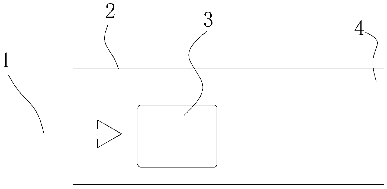
[0048] Its working principle is that the light input by the optical fiber is focused by the lens and then projected onto the object to be detected. The reflected light generated by the object returns to the system and interferes with the light of the reference arm of the OCT system. Specifically, the light of the system It is divided into two parts by the optical splitter, one part enters the probe, and one part enters the reference arm, and the reflected light formed by the two enters the coupler for interference reaction. According to the interference spectrum, cross-sectional images at different depths can be obtained through systematic analysis.


PUM


Abstract

The invention discloses an optical fiber probe combining OCT imaging and pressure sensing. The probe has OCT imaging function and the pressure sensing function. The probe is provided with an optical fiber input part, a pipe body, an imaging assembly part and an FP cavity pressure sensing part. Imaging and pressure sensing can be combined, imaging and pressure sensing are synchronized, meanwhile, interface depth image information and pressure information of an object to be measured are obtained, and the experiment efficiency is effectively improved. And secondly, the structure of the probe is optimized, and the probe has the advantages of electromagnetic interference resistance and moisture resistance.

Description

technical field [0001] The invention relates to the technical field of medical equipment, in particular to an optical fiber probe combined with OCT imaging and pressure sensing and a pressure detection and imaging method thereof. Background technique [0002] There are the following problems in the existing methods: 1. In the experiment, the optical fiber probe cannot simultaneously obtain the pressure value information and the image information of the cross-sectional depth of the object under test. For example, when detecting vascular sclerosis, it is necessary to know the blockage depth. Statistics on blood flow velocity and pulse information are also needed to further determine the extent of vascular sclerosis and the impact of vascular sclerosis on blood flow. 2. Most of the pressure measuring probes used today are metal probes, which are large in size and high in cost, and are not suitable for detection in animal organisms. 3. The preparation of most pressure measuring...

Claims


Application Information

Patent Timeline
IPC IPC(8): G01D21/02A61B5/00A61B5/02
CPCA61B5/0033A61B5/0066A61B5/02G01D21/02
Inventor 梁姗姗程雪园
Owner SUN YAT SEN UNIV
Learn More