
Anti-collision roller way of industrial heating furnace

A heating furnace and anti-collision technology, applied in the field of heating furnace roller table, can solve problems such as rebound, and achieve the effect of ensuring effective operation, large cross-sectional area of ​​oil circuit, and ensuring safety

Pending Publication Date: 2020-08-11
王屹
View PDF6 Cites 0 Cited by
  • Summary
  • Abstract
  • Description
  • Claims
  • Application Information

AI Technical Summary

Problems solved by technology

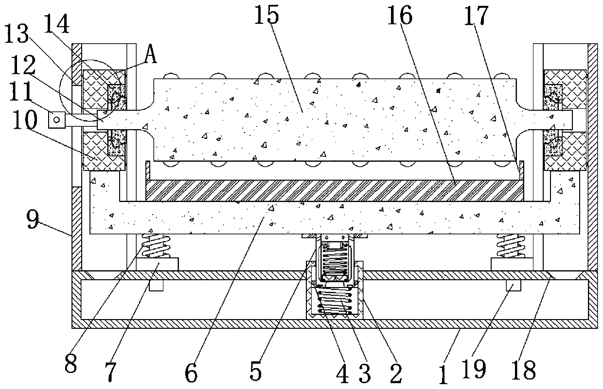
[0004] Based on the technical problem that the existing anti-shock roller table will bounce back after being subjected to a violent impact from above, the present invention proposes an anti-shock roller table for industrial heating furnaces

Method used


Image

  • Anti-collision roller way of industrial heating furnace
  • Anti-collision roller way of industrial heating furnace
  • Anti-collision roller way of industrial heating furnace

Examples


Embodiment 1

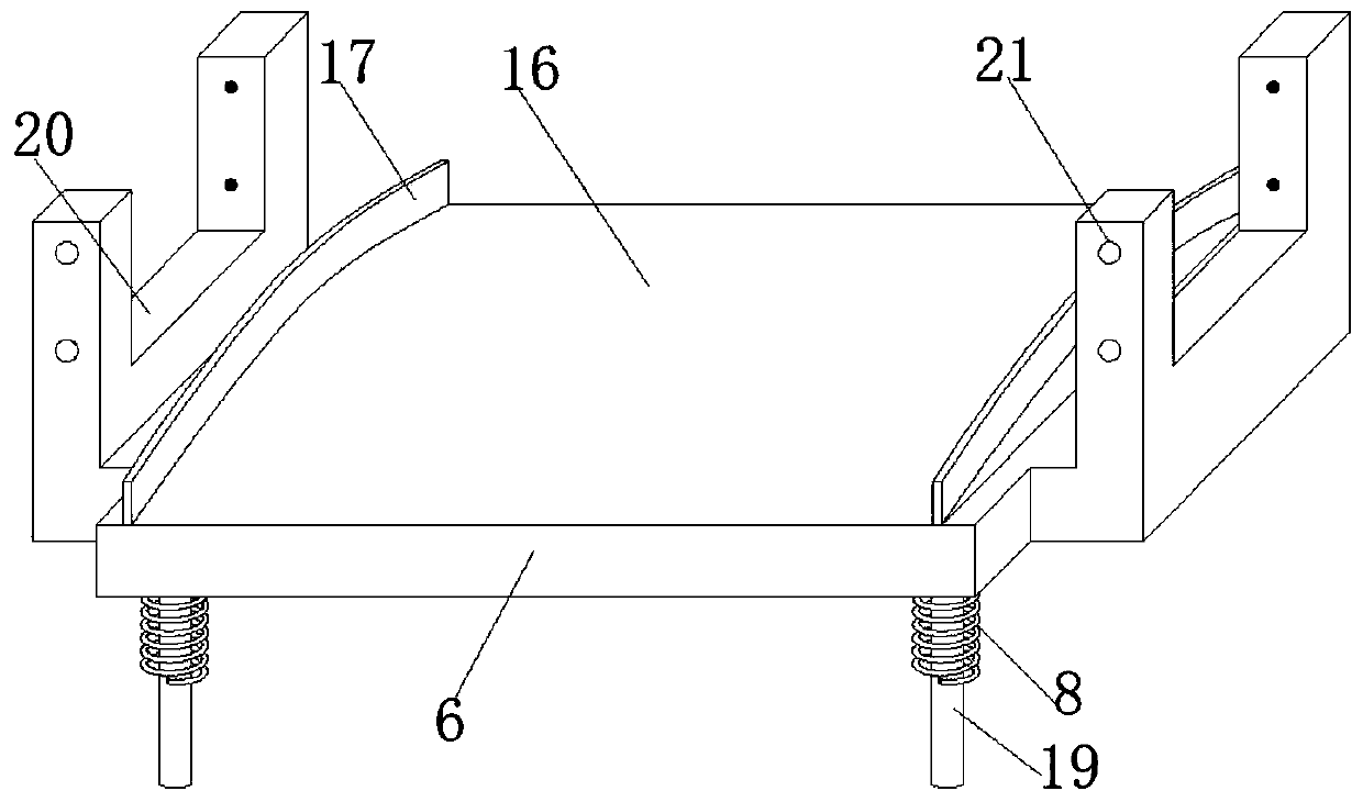
[0029] refer to Figure 1-5 , an anti-collision roller table for an industrial heating furnace, including a support seat 1 with a cavity inside and a cuboid structure, the upper surface of the support seat 1 is respectively fixed with C-shaped steel columns 9 with openings opposite to each other, and two C-shaped steel columns The chute of 9 is slidably connected with a bearing seat 10, and the same transport roller 15 is rotatably connected between the two bearing seats 10, and the same U-shaped bracket with an upward opening is fixed between the lower surfaces of the two bearing seats 10. Plate 6, the lower surface of U-shaped supporting plate 6 is all fixed with guide rod 19 near the four corners, and the side of C-shaped steel column 9 is welded with guide ring 7 matching with guide rod 19 near the bottom end, and guide The upper surface of the ring 7 is fixed with a buffer spring 8, the density of the buffer spring 8 near the bottom is greater than the density at the top,...

Embodiment 2

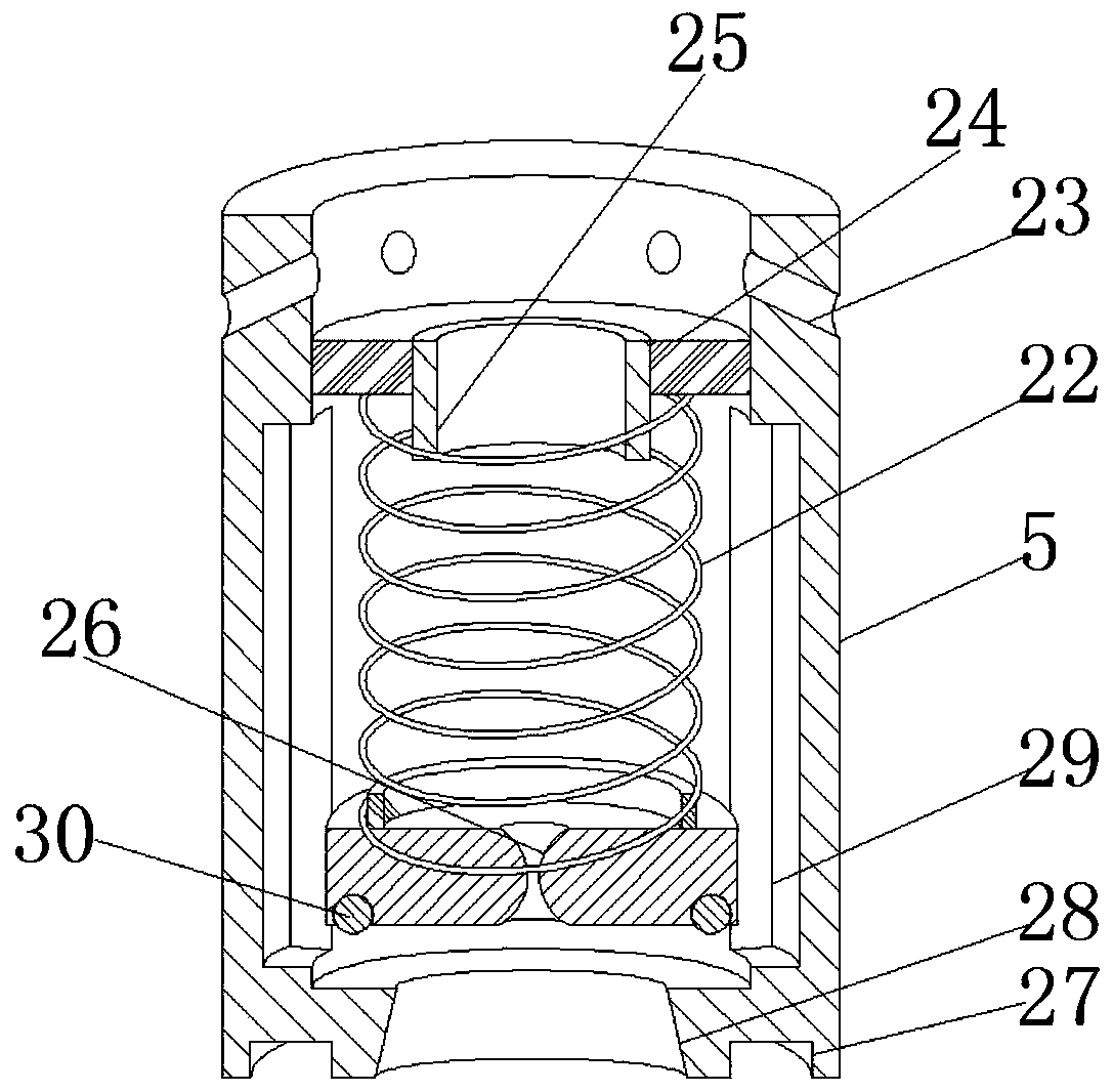
[0039] refer to figure 1 with image 3 , an anti-collision roller table for an industrial heating furnace. Compared with Embodiment 1, this embodiment also includes two mutually symmetrical rectangular grooves 29 on the inner wall of the inner barrel 5 .

[0040] Working principle: The transmission effect of the hydraulic oil is improved, the cross-sectional area of ​​the oil circuit becomes larger, the up and down operation of the hydraulic oil is smoother, and the high-quality operation of the device is ensured.


PUM


Abstract

The invention belongs to the technical field of heating furnace roller ways, and particularly relates to an anti-collision roller way of an industrial heating furnace. The anti-collision roller way ofthe industrial heating furnace aims to solve the problem that an existing anti-collision roller way can rebound after being subjected to violent impact from the upper portion. According to the following scheme, the anti-collision roller way of the industrial heating furnace comprises a supporting seat, wherein a cavity is formed in the supporting seat, and the supporting seat is of a cuboid structure; C-shaped steel stand columns with opposite openings are fixed to the positions, close to the two ends, of the upper surface of the supporting seat correspondingly, and bearing seats are slidablyconnected into sliding grooves of the two C-shaped steel stand columns correspondingly; a same conveying roller is rotationally connected between the two bearing seats, and a same U-shaped supportingplate with an upward opening is fixed between the lower surfaces of the two bearing seats; and guide rods are fixed to the positions, close to the four corners, of the lower surface of the U-shaped supporting plate correspondingly. According to the anti-collision roller way of the industrial heating furnace, when the upper portion of the roller way is suddenly subjected to violent impact in the using process, the impact force can be dispersed to four buffer springs at the bottom at the first time, and the closer the springs are to the bottom end, the stronger the counter-acting force of the springs is.

Description

technical field [0001] The invention relates to the technical field of heating furnace roller tables, in particular to an anti-collision roller table for industrial heating furnaces. Background technique [0002] During the production process of steel ingots in heavy plate factories, due to the heavy weight of steel ingots, when the crane lifts and places them on the conveying roller table, the steel ingot has a great impact on the roller table, which is easy to cause damage to the roller table and seriously affects the roller table conveying rollers. The service life will increase the consumption of spare parts and expenses, especially when hoisting above the roller table at the feed inlet of the heating furnace, special attention must be paid, because the temperature here is very high and it is not easy to overhaul. If it is smashed, the furnace needs to be shut down for repairs, and the economic losses caused are difficult to underestimate. [0003] After searching, the ...

Claims


Application Information

Patent Timeline
IPC IPC(8): F27D3/02F27D21/00
CPCF27D3/028F27D21/00F27D2021/0092
Inventor 王屹
Owner 王屹
Learn More