Double-side laser wire melting welding device and welding method for thin-plate T-shaped joint
The technology of a welding device and welding method is applied in the field of laser fuse welding devices on both sides of thin plate T-joints, which can solve problems such as keyhole fluctuation, influence on weld quality, and insufficient welding wire melting, so as to reduce deformation and improve welding efficiency. Seam quality, improve the effect of laser energy utilization
- Summary
- Abstract
- Description
- Claims
- Application Information
AI Technical Summary
Problems solved by technology
Method used
Image
Examples
Embodiment 1
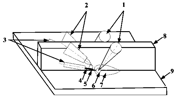
[0031] like figure 1 Shown is a thin-plate T-joint double-sided laser fuse welding device, the welding device includes two sets of identical welding assemblies, and when welding the T-joint, the two sets of welding assemblies are respectively located on both sides of the vertical plate 8, each The set of welding assemblies includes a laser that generates a laser beam 1, a TIG welding torch 2 and a TIG power supply 10, and the laser beam 1 in each set of said welding assemblies is irradiated at the junction of one side of the vertical plate 8 and the bottom plate 9, and a spoon is formed there. hole 6 and molten pool 7, the negative pole of the TIG power supply 10 is connected to the TIG welding gun 2, and the positive pole is connected to the welding wire 4, thereby forming a fuse arc 5 between the welding wire 4 and the end of the TIG welding gun 2, and the fuse arc 5 It is not in contact with the vertical plate 8 , the bottom plate 9 and the molten pool 7 , and the liquid me...
Embodiment 2
[0037] This embodiment is an optimized and limited solution to the solution of Example 1. The width of the slit reserved between the vertical plate 8 and the bottom plate 9 is preferably 0.01-0.2 mm, so that it is formed by melting the welding wire 4 Liquid metal forms a capillary attraction effect.
[0038] In this embodiment, the reserved slit width between the vertical plate 8 and the bottom plate 9 is more preferably 0.01-0.1 mm.
Embodiment 3
[0040] This embodiment is another optimized and limited solution to the solution of embodiment 1. The distance between the fuse arc 5 and the vertical plate 8 is 3-5 mm, and the distance between the fuse arc 5 and the bottom plate 9 is 3-5 mm. The distance between the fuse arc 5 and the molten pool 7 is 0.2-1.6mm.
PUM
 Abstract
Description
Claims
Application Information
 - R&D
- Intellectual Property
- Life Sciences
- Materials
- Tech Scout
- Unparalleled Data Quality
- Higher Quality Content
- 60% Fewer Hallucinations
Browse by: Latest US Patents, China's latest patents, Technical Efficacy Thesaurus, Application Domain, Technology Topic, Popular Technical Reports.
© 2025 PatSnap. All rights reserved.Legal|Privacy policy|Modern Slavery Act Transparency Statement|Sitemap|About US| Contact US: help@patsnap.com


