A kind of microbial fermented feed preparation device and its preparation
A technology of microbial fermentation and preparation equipment, applied in feed, grain processing, food science, etc., to achieve the effect of ensuring continuous operation
- Summary
- Abstract
- Description
- Claims
- Application Information
AI Technical Summary
Problems solved by technology
Method used
Image
Examples
Embodiment 1
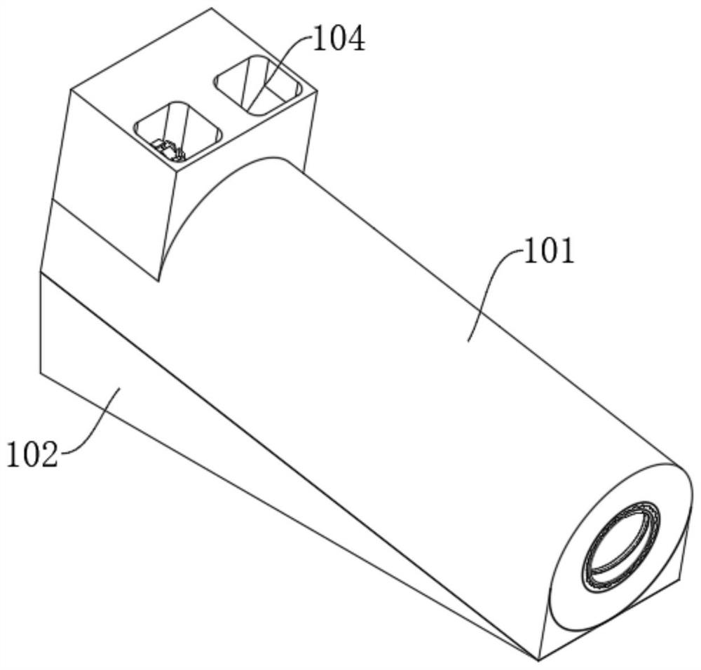
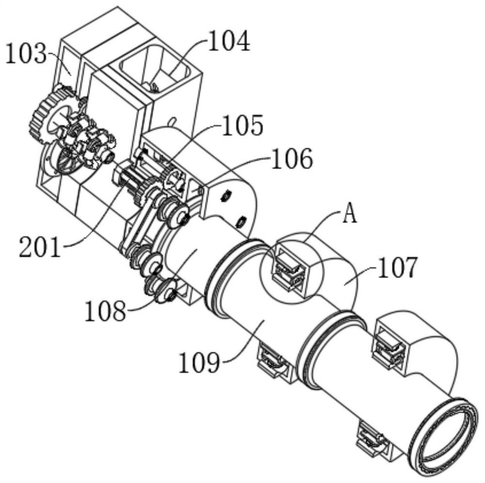
[0028] A microbial fermentation feed preparation device and preparation thereof, comprising: a main body support shell 101 and a support base 102, the main body support shell 101 is fixedly installed on the upper end of the support base 102, and the main body support shell 101 is sequentially provided with a transmission bin 103, an inlet The silo 104, the drive bin 105, the linkage bin 106 and the outer protection bin 107. The drive bin 105 is fixedly installed with a drive mechanism. The front end of the drive mechanism is fixedly connected to the upper side of the linkage mechanism. The linkage mechanism is fixedly installed inside the linkage bin 106. The drive mechanism The rear side is movably connected with the crushing mechanism, the crushing mechanism is movably installed inside the feeding bin 104, the rear end of the driving mechanism is fixedly connected with the upper side of the blowing and blocking mechanism, the blowing and blocking mechanism is movably installed...
Embodiment 2
[0031] Example 2: Based on Example 1, but with the following differences:
[0032] The driving mechanism includes: a servo motor 201, a rotating gear 202, a fixed gear 203, a fixed shaft 204 and a transmission gear 205. A servo motor 201 is fixedly installed on the upper and lower sides of the drive compartment 105. The front end of the main shaft of the servo motor 201 is connected with the rotating gear 202 and The upper side of the linkage mechanism is fixedly connected, the inner side of the rotating gear 202 is meshed with the front and rear sides of the fixed gear 203, the axis of the fixed gear 203 is fixedly connected with the right side of the fixed shaft 204, and the left side of the fixed shaft 204 is fixed with the transmission gear 205. The front and rear sides of the transmission gear 205 are meshed and connected with the crushing mechanism, the left end of the fixed shaft 204 is fixedly connected with the upper side of the blowing and blocking mechanism, and the ...
Embodiment 3
[0037] Example 3: Based on Examples 1 and 2, but with the following differences:
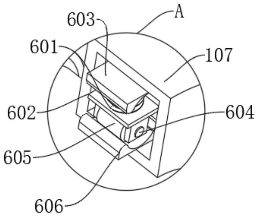
[0038] The buffer mechanism includes: a stress spring 601, a spring base 602, a connecting base 603, a lateral rotation shaft 604, a roller 605 and a limit base 606, the inner wall of the outer protection chamber 107 is fixedly connected with the limit base 606, and the upper side of the limit base 606 is connected with the roller 605 Actively connected, the axis of the roller 605 is fixedly connected with the transverse shaft 604, the left and right sides of the transverse shaft 604 are movably connected with the inner walls of the left and right sides of the spring base 602, the upper surface of the spring base 602 is fixedly connected with the lower end of the stress spring 601, and the upper end of the stress spring 601 is connected with The lower surface of the base 603 is fixedly connected, and the upper surface of the connection base 603 is fixedly connected to the inner wall of the outer ...
PUM
 Abstract
Description
Claims
Application Information
 - R&D
- Intellectual Property
- Life Sciences
- Materials
- Tech Scout
- Unparalleled Data Quality
- Higher Quality Content
- 60% Fewer Hallucinations
Browse by: Latest US Patents, China's latest patents, Technical Efficacy Thesaurus, Application Domain, Technology Topic, Popular Technical Reports.
© 2025 PatSnap. All rights reserved.Legal|Privacy policy|Modern Slavery Act Transparency Statement|Sitemap|About US| Contact US: help@patsnap.com


