
Efficient flow-guiding filter

A filter and high-efficiency technology, which is applied in fixed filter element filters, filtration and separation, chemical instruments and methods, etc., can solve the problems of uneven mixing of additives and high difficulty in stirring, and achieve uneven mixing of ingredients, low production costs, simple structure

Active Publication Date: 2019-05-07
浙江国涛滤料科技有限公司
View PDF9 Cites 0 Cited by
  • Summary
  • Abstract
  • Description
  • Claims
  • Application Information

AI Technical Summary

Problems solved by technology

[0002] At present, in the process of wastewater treatment, due to the existence of various toxic and harmful substances, foams and suspended objects in the wastewater, it is necessary to filter the foams and suspended objects, and at the same time add some additives to purify the wastewater so that the wastewater reaches the specified level. However, the current filter generally has a complex structure or directly uses steel wire mesh to filter foam and suspended solids. Although it has the effect of filtering, it can only be filtered by taking the steel mesh out of the water surface when removing it. However, when additives are mixed into the liquid, because the mixed liquid has not been stirred or some solid or powdery objects cannot be effectively mixed into the wastewater, the additives in the wastewater are mixed unevenly, or several additives need to be mixed. When re-adding, another container is required for mixing, and the mixing is difficult

Method used


Image

  • Efficient flow-guiding filter
  • Efficient flow-guiding filter
  • Efficient flow-guiding filter

Examples


Embodiment Construction

[0023] Below, the present invention will be further described in conjunction with the accompanying drawings and specific implementation methods. It should be noted that, under the premise of not conflicting, the various embodiments described below or the technical features can be combined arbitrarily to form new embodiments. .

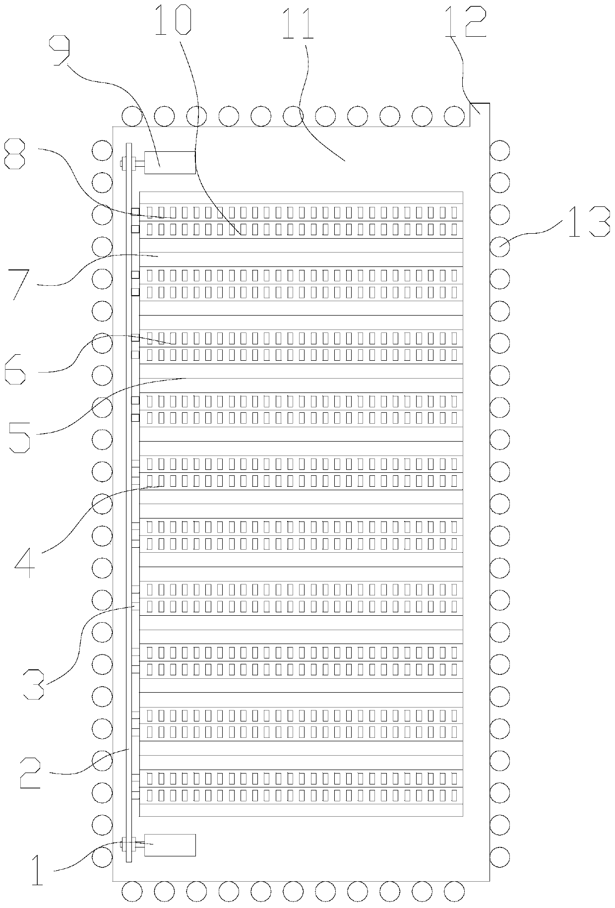
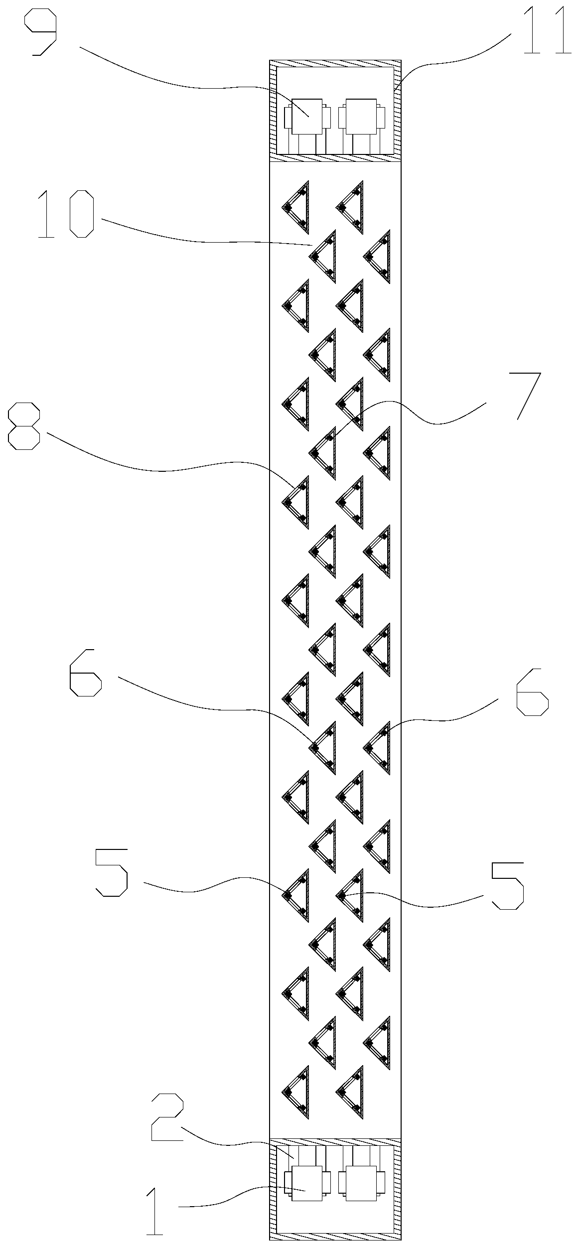
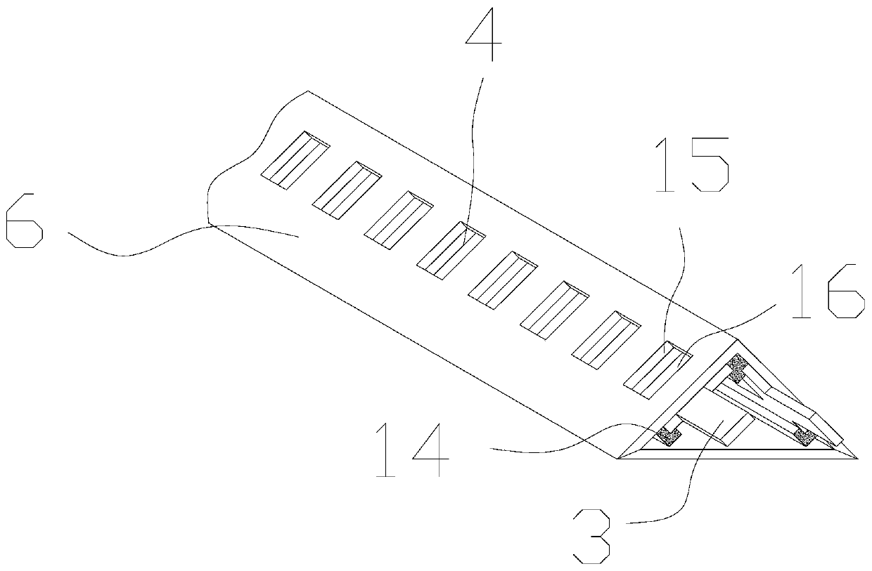
[0024] Such as Figure 1-5 As shown, a high-efficiency diversion filter includes a quadrangular mounting frame 11 formed by connecting four hollow rectangular metal plates end to end, at least one set of filter layers 10 arranged in the mounting frame 11, and the filter layer 10 includes a distribution layer 8 and a mixing layer 7 arranged sequentially from top to bottom, the distribution layer 8 is composed of a number of distribution pipes 6 horizontally arranged in the installation frame 11, and the mixing layer 7 is composed of several horizontally arranged in the installation frame 11 The mixed flow tube 5 inside is composed of the cross-section ...


PUM


Abstract

The invention provides an efficient flow-guiding filter. The efficient flow-guiding filter comprises an installation frame and a filtering layer which is arranged in the installation frame, wherein the filtering layer comprises a flow-splitting layer and a mixing layer, the flow-splitting layer is composed of a plurality of flow-splitting pipes which are horizontally arranged in the installation frame, the mixing layer is composed of a plurality of flow-mixing pipes which are horizontally arranged in the installation frame, cross sections of the flow-splitting pipes and the flow-mixing pipes are all of structures of isosceles right triangles, top angles of the flow-splitting pipes and the flow-mixing pipes all face upwards, side surfaces formed by each two right-angle edges are symmetrically arranged on the two sides of one corresponding top angle, distance between each two adjacent flow-splitting pipe and flow-mixing pipe is smaller than distance of hypotenuses of the corresponding isosceles right triangles, the top angle of each corresponding flow-mixing pipe is located between two corresponding adjacent flow-splitting pipes, a bevel extension area formed by the right-angle edgesof each corresponding flow-splitting pipe and two right-angle surfaces of the corresponding flow-mixing pipe are arranged in a crossed mode, and the angle between the bevel extension area formed by the right-angle edges of each corresponding flow-splitting pipe and two right-angle surfaces of the corresponding flow-mixing pipe is 90 degrees. Foam and suspension in liquid can be effectively filtered, and in a filtering process, the liquid which passes the filter can be fast and evenly mixed, so that the liquid and additives are mixed more evenly, the structure is simple, operation is simple and convenient, and the production cost is low.

Description

technical field [0001] The invention relates to the field of demister filters, in particular to high-efficiency diversion filters. Background technique [0002] At present, in the process of wastewater treatment, due to the existence of various toxic and harmful substances, foams and suspended objects in the wastewater, it is necessary to filter the foams and suspended objects, and at the same time add some additives to purify the wastewater so that the wastewater reaches the specified level. However, the current filter generally has a complex structure or directly uses steel wire mesh to filter foam and suspended solids. Although it has the effect of filtering, it can only be filtered by taking the steel mesh out of the water surface when removing it. However, when additives are mixed into the liquid, because the mixed liquid has not been stirred or some solid or powdery objects cannot be effectively mixed into the wastewater, the additives in the wastewater are mixed uneve...

Claims


Application Information

Patent Timeline
IPC IPC(8): B01D19/00B01D29/58
Inventor 庞伟杰
Owner 浙江国涛滤料科技有限公司
Learn More