
Auxiliary slow start and discharge circuit of bidirectional phase-shift full-bridge converter

A phase-shifting full-bridge and discharge circuit technology, applied in the direction of converting DC power input to DC power output, instruments, electrical components, etc. impact effect

Inactive Publication Date: 2020-08-07
SHENZHEN YINGFEIYUAN TECH CO LTD
View PDF12 Cites 0 Cited by
  • Summary
  • Abstract
  • Description
  • Claims
  • Application Information

AI Technical Summary

Problems solved by technology

[0003] The invention provides an auxiliary slow start and discharge circuit of a bidirectional phase-shift full-bridge converter, which is used to solve the technical problem of insufficient reliability of the start and discharge of the converter in the prior art

Method used


Image

  • Auxiliary slow start and discharge circuit of bidirectional phase-shift full-bridge converter
  • Auxiliary slow start and discharge circuit of bidirectional phase-shift full-bridge converter
  • Auxiliary slow start and discharge circuit of bidirectional phase-shift full-bridge converter

Examples


no. 1 example

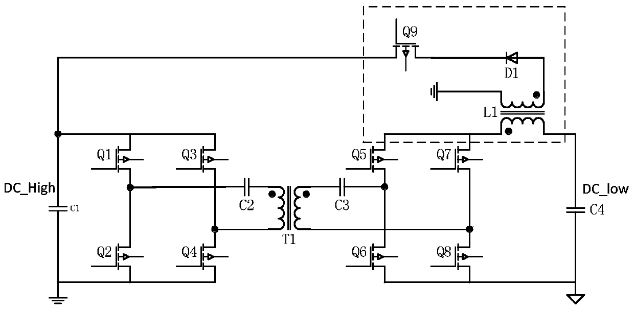
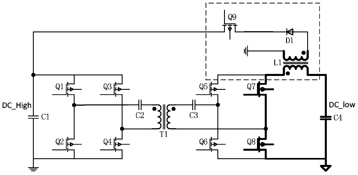
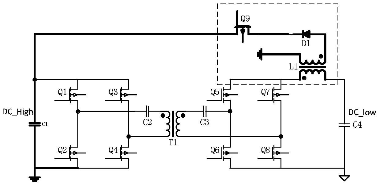
[0023] see figure 1 , the invention discloses an auxiliary slow start and discharge circuit for a bidirectional phase-shifting full-bridge converter, comprising a transformer T1, a first bridge switch unit, a second bridge switch unit, a first filter capacitor C1, a second filter capacitor C4 and flyback transformer L1.

[0024] Specifically, the first bridge switch unit includes a first switching tube Q1, a second switching tube Q2, a third switching tube Q3, and a fourth switching tube Q4, and one end of the first switching tube Q1 and one end of the second switching tube Q2 are both One end of the high-voltage side coil of the transformer T1 is electrically connected, one end of the third switching tube Q3 and one end of the fourth switching tube Q4 are electrically connected to the other end of the high-voltage side coil of the transformer T1, the other end of the first switching tube Q1 is connected to the third The other end of the switching tube Q3 is electrically conn...

no. 2 example

[0035] see further Figure 5 , and the difference from the first embodiment is that the second DC blocking capacitor C3 is not included in this embodiment, and the current connected to the transformer is AC, which needs to be processed by DC blocking capacitors. In this embodiment, the low-voltage side The DC blocking capacitor is canceled, and the DC blocking capacitor on the high voltage side can be retained.

no. 3 example

[0037] see further Image 6 , the difference from the first embodiment is that the first DC blocking capacitor C2 is not included in this embodiment, and the current connected to the transformer is all AC, which needs to be processed by DC blocking capacitors. In this embodiment, the high-voltage side The DC blocking capacitor is canceled, and the DC blocking capacitor on the low voltage side can be retained.


PUM


Abstract

The invention relates to an auxiliary slow start and discharge circuit of a bidirectional phase-shifting full-bridge converter. The circuit comprises a transformer, a first bridge type switch unit, asecond bridge type switch unit, a first filter capacitor, a second filter capacitor and a flyback transformer, the first bridge type switch unit is arranged in the high-voltage side of the transformerand is electrically connected with the two ends of the first filter capacitor; the second bridge type switch unit is arranged in the low-voltage side of the transformer and is electrically connectedwith the two ends of the second filter capacitor; a first coil of the flyback transformer is electrically connected with the first filter capacitor and the first bridge type switch unit, and a secondcoil of the flyback transformer is connected between the second filter capacitor and the second bridge type switch unit.

Description

technical field [0001] The invention belongs to the technical field of electronic products, in particular to an auxiliary slow start and discharge circuit of a bidirectional phase-shifting full-bridge converter. Background technique [0002] With the development of society and the progress of human society, energy problems are becoming more and more serious, and people begin to focus on the use of renewable energy. However, renewable energy has intermittent and random problems, and energy storage devices need to be introduced to provide continuous power. The energy storage device generally controls the bidirectional transmission of energy through a bidirectional DC-DC converter. Contents of the invention [0003] The invention provides an auxiliary slow start and discharge circuit of a bidirectional phase-shifting full-bridge converter, which is used to solve the technical problem of insufficient reliability of the start and discharge of the converter in the prior art. ...

Claims


Application Information

Patent Timeline
IPC IPC(8): H02M3/335H02M1/32H02M1/14
CPCH02M3/33584H02M1/32H02M1/14
Inventor 刘志敏杨明聪
Owner SHENZHEN YINGFEIYUAN TECH CO LTD
Learn More