Millimeter wave radar array antenna

A millimeter-wave radar and array antenna technology, which is applied in directions such as antennas, antenna arrays, and individually powered antenna arrays. The overall detection performance, the effect of solving the loss, and improving the impedance matching characteristics

Inactive Publication Date: 2020-08-07
CHENGDU UNIVERSITY OF TECHNOLOGY
View PDF2 Cites 1 Cited by
  • Summary
  • Abstract
  • Description
  • Claims
  • Application Information

AI Technical Summary

Problems solved by technology

At present, the existing domestic millimeter wave antenna structure in the domestic market mainly adopts the traditional microstrip line series feed structure or series feed array structure, the transmission line loss is large, and the antenna gain is limited. At present, most domestic radar products still maintain a detection distance of 200 meters The level of left and right cannot meet the application requirements of long-range radar

Method used


Image

  • Millimeter wave radar array antenna
  • Millimeter wave radar array antenna
  • Millimeter wave radar array antenna

Examples


Embodiment Construction

[0022] The technical solutions in the embodiments of the present invention will be clearly and completely described below in conjunction with the accompanying drawings in the embodiments of the present invention. Obviously, the described embodiments are only a part of the embodiments of the present invention, rather than all the embodiments. Based on the embodiments of the present invention, all other embodiments obtained by those skilled in the art without any creative work shall fall within the protection scope of the present invention.

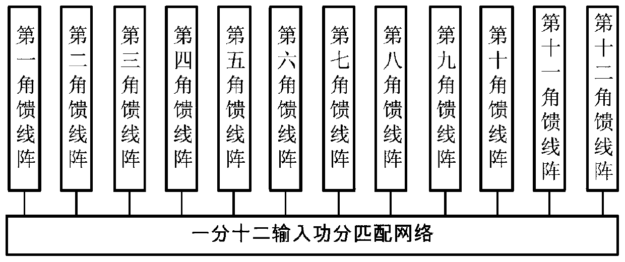
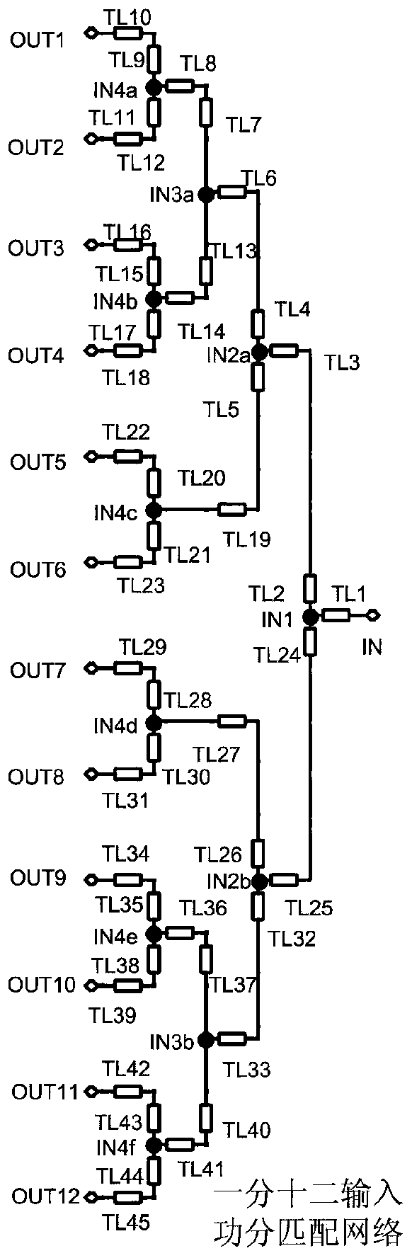
[0023] The millimeter wave radar array antenna provided in this embodiment includes a one-to-two input power-division matching network, and a first to twelfth corner feeder array;

[0024] Such as figure 1 As shown, the input end of the one-to-two input power division matching network is the input of the entire millimeter wave radar array antenna; the first to twelfth output ends of the one-to-two input power division matching network are sequent...


PUM


Abstract

The invention discloses a millimeter wave radar array antenna which a one-to-twelve input power division matching network and first to twelfth angular feeder arrays. The core architecture of the invention adopts an in-phase non-equal amplitude angle feed ten-element structure, and a corner cut circular polarization method of a symmetrical structure and a combination method of surface slotting arecombined to control the size and position of an antenna parasitic unit, the antenna sidelobe level is reasonably suppressed and the radiation characteristics of the antenna is optimized. Meanwhile, amultilayer substrate design structure and a TSV interconnection technology are utilized, the signal interference of an antenna feeder structure on an antenna resonance unit is reasonably avoided, thedielectric loss is reduced, the radar detection sensitivity and overall detection performance are improved, and circuit integration and equipment miniaturization are facilitated.

Description

Technical field [0001] The invention relates to the technical field of vehicle-mounted millimeter wave radar array antennas, in particular to a millimeter wave radar array antenna. Background technique [0002] In recent years, with the development of radar technology, the volume of radar has become smaller and smaller, and the cost has been continuously reduced, which makes it possible for radar to be used in the field of automobile collision avoidance. Car collision avoidance radar is a kind of car assisted driving system that can provide early warning or directly intervene in driver's operation to prevent accidents. Car collision avoidance radars can be divided into three types: long-range radar, medium-range radar and short-range radar according to their range. Each type has different requirements for antenna performance. Long-range radars can measure up to 100 meters or more. The radar beams are also very narrow and have excellent directivity. Long-range radars generally re...

Claims


Application Information

Patent Timeline
IPC IPC(8): H01Q1/36H01Q21/06
CPCH01Q1/36H01Q21/061H01Q21/065
Inventor 刘林盛邬海峰
Owner CHENGDU UNIVERSITY OF TECHNOLOGY
Why Eureka
Try Eureka