Digital gas density relay with self-diagnosis function and self-diagnosis method of relay
A technology of gas density and self-diagnosis, applied in the power field, can solve problems such as hidden dangers in safe operation and affecting electrical performance of equipment
- Summary
- Abstract
- Description
- Claims
- Application Information
AI Technical Summary
Problems solved by technology
Method used
Image
Examples
Embodiment 1
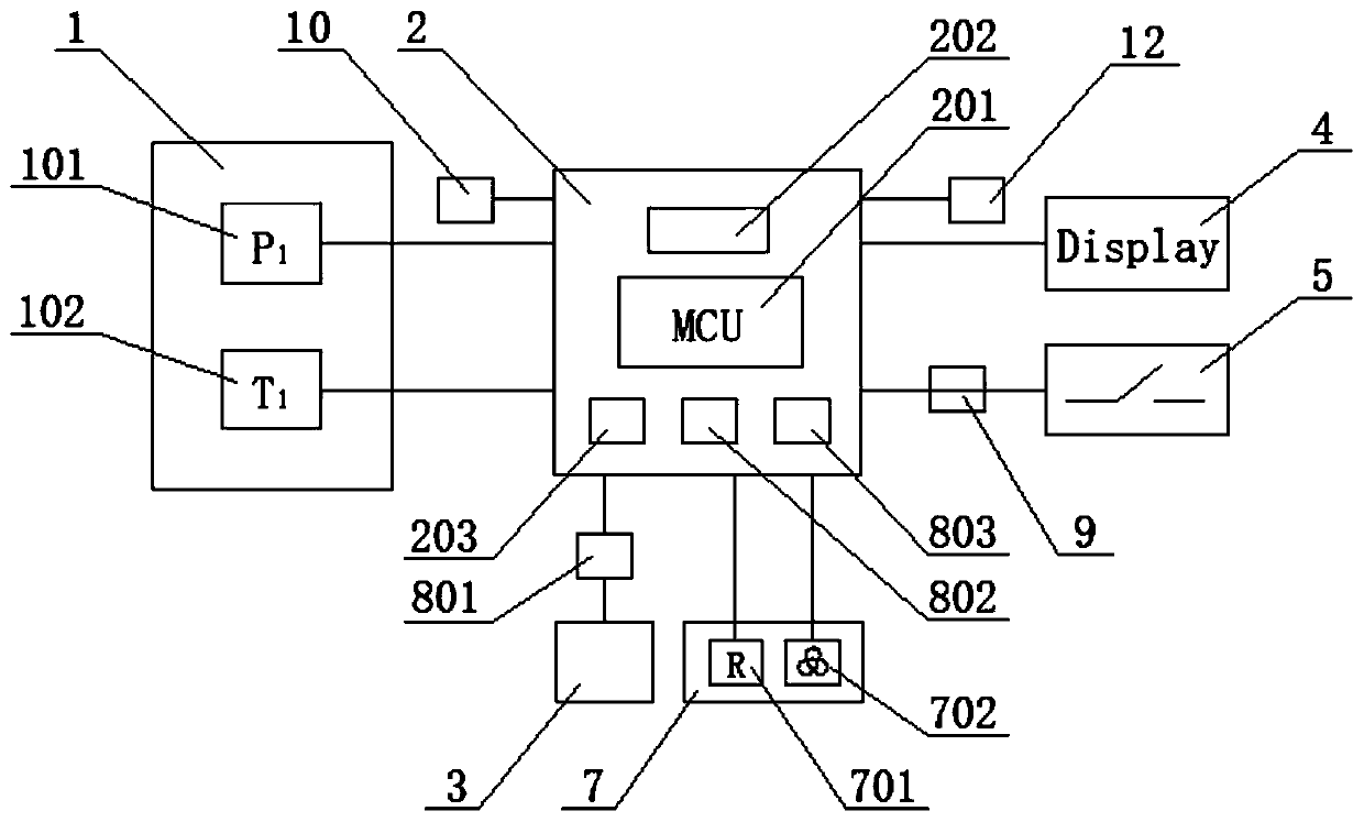
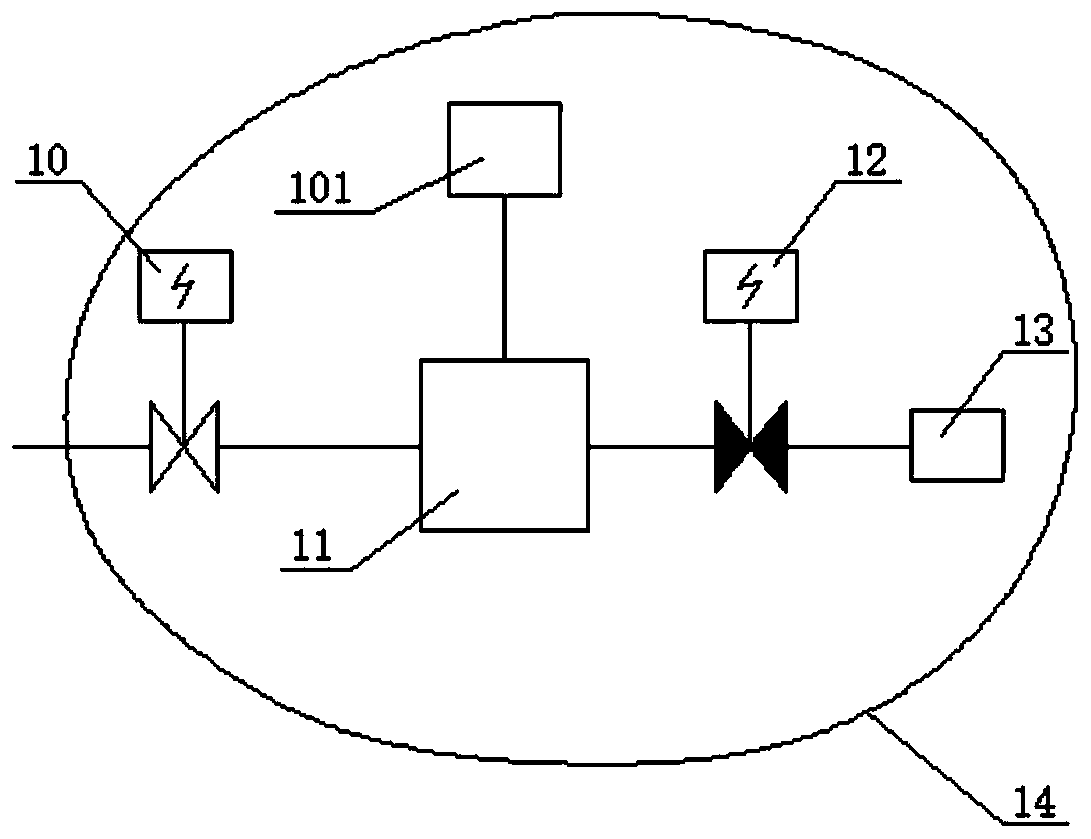
[0105] figure 1 It is a schematic diagram of the circuit principle of a digital gas density relay with self-diagnosis function for high and medium voltage electrical equipment in the first embodiment of the present invention, figure 2 It is a schematic diagram of the gas circuit structure of a digital gas density relay or gas density monitoring device with self-diagnosis function for high and medium voltage electrical equipment of the first embodiment.
[0106] Such as figure 1 with figure 2 As shown, a digital gas density relay or gas density monitoring device with self-diagnosis function includes: a digital gas density relay housing 14, a gas density detection sensor 1, an intelligent control unit 2, a communication module 3, and a display unit 4 , Annunciator 5, temperature control unit 7, protection circuit (surge protection circuit 801, filter circuit 802, short circuit protection circuit 803), short circuit and / or open circuit diagnostic circuit 9, normally open electronic ...
Embodiment 2
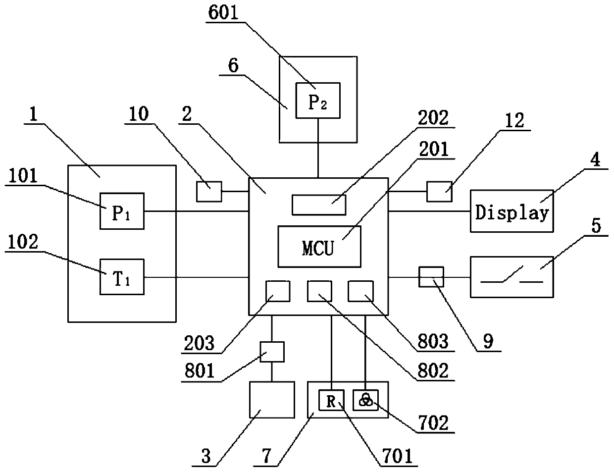
[0122] image 3 It is a schematic diagram of the circuit principle of a digital gas density relay or gas density monitoring device with self-diagnosis function for high and medium voltage electrical equipment of the second embodiment; Figure 4 It is a schematic diagram of the gas circuit structure of a digital gas density relay or gas density monitoring device with self-diagnosis function for high and medium voltage electrical equipment of the second embodiment.
[0123] Such as image 3 with Figure 4 As shown, the difference from the first embodiment is that in this embodiment, a comparison sensor 6 is further included, and the comparison sensor 6 includes a second pressure sensor 601. On the gas path, the pressure sensor 101 of the gas density detection sensor 1 and the second pressure sensor 601 of the comparison sensor 6 are respectively connected to the multi-way connector 11. The normally open electronic control valve 10 is configured to shut off the gas density detection ...
Embodiment 3
[0132] Such as Figure 5 The difference from the second embodiment is that in this embodiment, the comparison sensor 6 includes a second pressure sensor 601 and a second temperature sensor 602. On the gas path, the pressure sensor 101 of the gas density detection sensor 1 and the second pressure sensor 601 of the comparison sensor 6 are respectively connected to the multi-way connector 11.
[0133] Specifically, the pressure value collected by the pressure sensor 101 of the gas density detection sensor 1 is the first pressure value P1, and the temperature value collected by the temperature sensor 102 is the first temperature value T1; compare the pressure value collected by the second pressure sensor 601 of the sensor 6 The pressure value is the second pressure value P2, and the temperature value collected by the second temperature sensor 602 is the second temperature value T2. Or, the gas density value collected by the gas density detection sensor 1 is the first density value P1...
PUM
 Abstract
Description
Claims
Application Information
 - R&D
- Intellectual Property
- Life Sciences
- Materials
- Tech Scout
- Unparalleled Data Quality
- Higher Quality Content
- 60% Fewer Hallucinations
Browse by: Latest US Patents, China's latest patents, Technical Efficacy Thesaurus, Application Domain, Technology Topic, Popular Technical Reports.
© 2025 PatSnap. All rights reserved.Legal|Privacy policy|Modern Slavery Act Transparency Statement|Sitemap|About US| Contact US: help@patsnap.com


