Pulse-type time-lapse dispersion spectroscopy measurement method and device, and spectral imaging method and device
A spectral measurement and spectral imaging technology, applied in the field of spectral measurement and spectral imaging, can solve the problems of insufficient detection sensitivity of spectrometers and low spectral measurement efficiency, and achieve the effects of improving photon utilization, improving spectral measurement efficiency, and efficient utilization
- Summary
- Abstract
- Description
- Claims
- Application Information
AI Technical Summary
Problems solved by technology
Method used
Image
Examples
example 1
[0066] Example 1: An example of time-lapse dispersion spontaneous Raman spectroscopy measurement and spectral imaging based on pulse excitation.
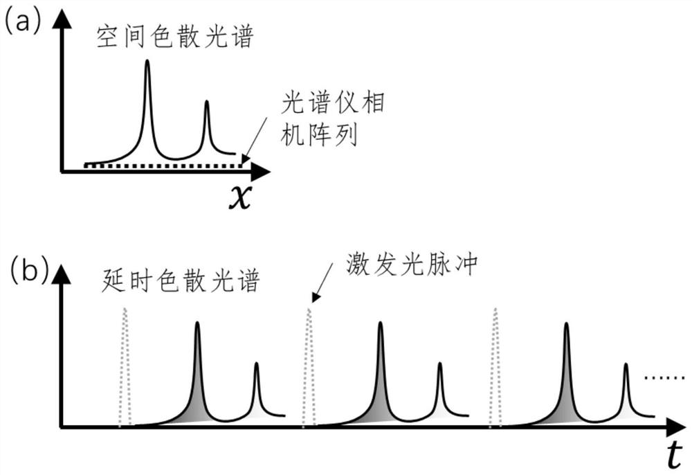
[0067] figure 1 It is a principle diagram based on the time-delay dispersion spectroscopy measurement based on pulse excitation, wherein (a) is a schematic diagram of the spectrum obtained based on the existing spatial dispersion spectroscopy method, and (b) is the spectrum obtained according to the time-delay dispersion spectroscopy method provided by the present invention Schematic; from figure 1 In (a), it can be seen that the spectrum is dispersed in space, and many pixels of the camera array using the spectrometer are detecting different components of the spectrum, but the sensitivity of the array pixels is generally low, and the photon utilization rate is poor. From figure 1 In (b), it can be seen that the spectra are separated in the time dimension, the dotted line is the short pulse of excitation light, and the solid lin...
example 2
[0076] Example 2: Example of time-lapse dispersion CARS spectrum measurement and CARS spectrum imaging.
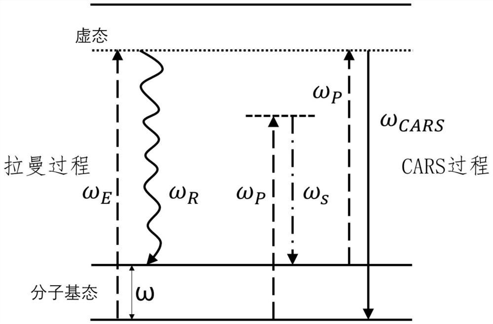
[0077] When the excitation laser is two synchronized and phase-locked pulse sources ω P , ω s , where ω P and ω s , usually pump light and Stokes light; when ω P and ω s When the energy difference between photons is consistent with the molecular vibrational energy level difference, an anti-Stokes photon ω CARS ,Such as figure 2 shown.
[0078] The embodiment of the present invention provides a method for time-lapse dispersion CARS spectrum measurement and CARS spectrum imaging, please refer to Figure 6 , and various system parameters can be selected according to the actual situation.
[0079]The pulse-type time-lapse dispersion spectroscopy imaging device provided by the embodiment of the present invention includes: a dual-channel pulsed laser generation module 200, a first power adjustment module 201, a second power adjustment module 202, an optical modulation m...
example 3
[0084] Example 3: A specific structural example of three delay dispersion modules.
[0085] The embodiment of the present invention provides three examples of generating time-delayed dispersion spectra. see reference Figure 8 , and various system parameters and methods can be selected according to the actual situation. The principle is as Figure 8 (a), the wavelength of the instantaneous spectrum generated by the pulsed laser is superimposed in time, and the photons in the spectrum can be separated in time and wavelength by using the method of time-delay dispersion and detected.
[0086] Figure 8 (b) shows the structure of the delay dispersion module based on the principle of fiber delay dispersion provided by the first embodiment. The fiber delay dispersion module includes: dispersion fiber 21, one end of which is connected to the photon collection module 106, and the other end is connected to the photoelectric The detection module 3 ; the photon collection module 106 ...
PUM
 Abstract
Description
Claims
Application Information
 - Generate Ideas
- Intellectual Property
- Life Sciences
- Materials
- Tech Scout
- Unparalleled Data Quality
- Higher Quality Content
- 60% Fewer Hallucinations
Browse by: Latest US Patents, China's latest patents, Technical Efficacy Thesaurus, Application Domain, Technology Topic, Popular Technical Reports.
© 2025 PatSnap. All rights reserved.Legal|Privacy policy|Modern Slavery Act Transparency Statement|Sitemap|About US| Contact US: help@patsnap.com


