Bearing steel ball loading test bench
A bearing steel ball, loading test technology, used in mechanical bearing testing, testing wear resistance, measuring devices, etc., can solve problems such as the inability to determine whether the bearing material has defects, the uncertainty of rolling element motion trajectories, and the damage of rolling elements. , to achieve the effect of simplifying the structure, reducing the number and improving the applicability
- Summary
- Abstract
- Description
- Claims
- Application Information
AI Technical Summary
Problems solved by technology
Method used
Image

Examples
Embodiment 2
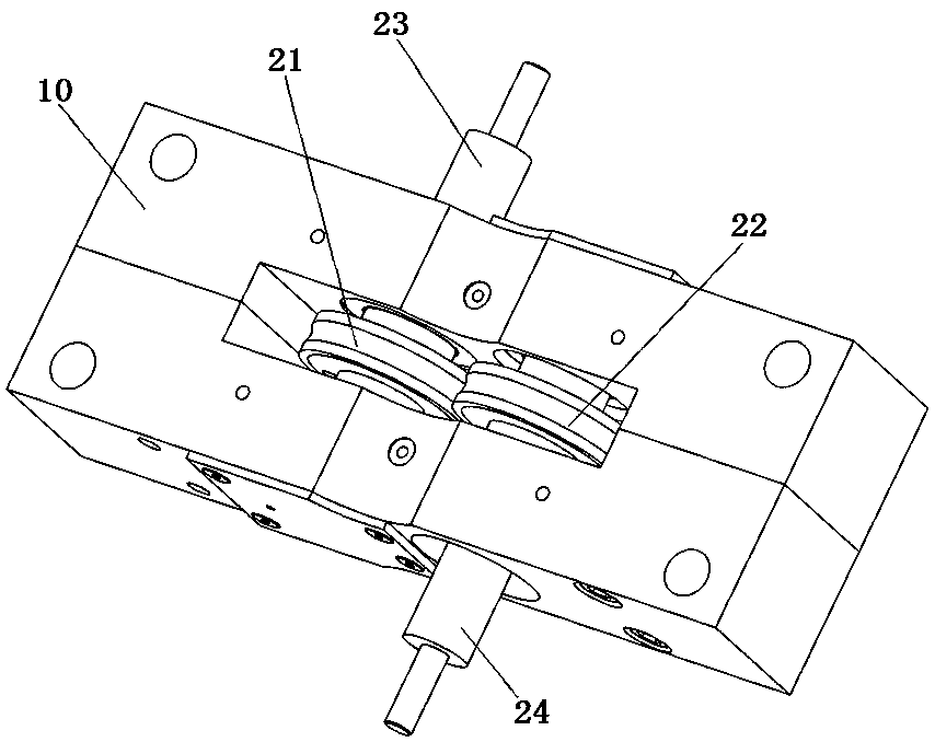
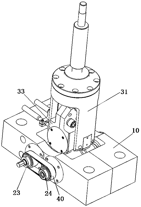
[0060] Embodiment 2 of the bearing steel ball loading test bench in the present invention: the difference from the above embodiment is that in this embodiment, as image 3 As shown, the wheel shafts of the two driving wheels in the test wheel set, that is, the left driving shaft 23 and the right driving shaft 24 cantilever in the same direction, and are assembled on the frame 10 through the rotation of the bearing seat. The rotary drive mechanism only uses one motor, and then the left drive shaft 23 and the right drive shaft 24 are connected through transmission belt 40. When the left drive shaft 23 rotates, it can drive the right drive shaft 24 to rotate synchronously, and then drive the upper bearing The driven wheel in the seat 33 rotates. During the rotation of the driven wheel, the upper electric cylinder 31 can output dynamic load thereto. In other embodiments, the rotary drive mechanism connected to the two axles may use two motors, the two motors are arranged side by ...
Embodiment 3
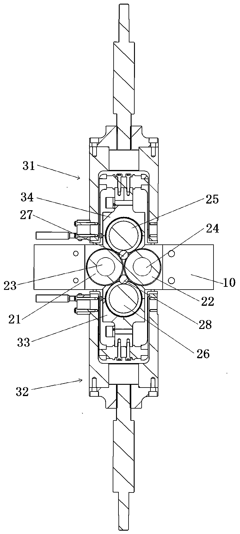
[0061] Embodiment 3 of the bearing steel ball loading test bench in the present invention: the difference from the above embodiment is that in this embodiment, the friction pair includes three driving wheels and one driven wheel, and the three driving wheels are in a V-shaped manner. Arrangement, the driven wheel is arranged between the three driving wheels. The three driving wheels are divided into the left driving wheel, the middle driving wheel and the right driving wheel. The driven wheel, the left driving wheel and the middle driving wheel constitute a left test wheel group. The driven wheel, the right driving wheel and the middle driving wheel The wheels constitute a right-hand test wheel set, and a bearing steel ball is placed in each test wheel set. Among them, each driving wheel is independently connected with a rotating drive mechanism to drive it to rotate, while the driven wheel is still arranged at the bottom of the driving rod. Driven by the rod, it is moving ag...
Embodiment 4
[0062] Embodiment 4 of the bearing steel ball loading test bench in the present invention: the difference from the above embodiment is that the friction pair in this embodiment includes two driving wheels and a driven wheel, and the driving wheel includes a left driving wheel and a right side Driving wheel, the friction wheel of each driving wheel and the anti-rotation assembly of corresponding driving shaft. The driven wheel is positioned directly above the midpoint of the line between the left driving wheel and the right driving wheel. Among them, the line connecting the axes of the left driving wheel, the right driving wheel and the driven wheel forms a triangle, and the left driving wheel, the right driving wheel and the driven wheel are respectively located on the three vertices of the triangle, and 1. In the space surrounded by the driving wheel on the right side and the driven wheel, it is used to place bearing steel balls, and the bearing steel balls can contact with t...
PUM
 Abstract
Description
Claims
Application Information
 - R&D
- Intellectual Property
- Life Sciences
- Materials
- Tech Scout
- Unparalleled Data Quality
- Higher Quality Content
- 60% Fewer Hallucinations
Browse by: Latest US Patents, China's latest patents, Technical Efficacy Thesaurus, Application Domain, Technology Topic, Popular Technical Reports.
© 2025 PatSnap. All rights reserved.Legal|Privacy policy|Modern Slavery Act Transparency Statement|Sitemap|About US| Contact US: help@patsnap.com