A mems probe single-axis symmetric bending test structure and its pitch arm

A symmetrical bending and testing structure technology, applied in the direction of testing material strength by applying stable bending force, testing material strength by applying stable tension/pressure, measuring devices, etc., can solve the difficult problem of heat dissipation, and no palladium alloy probe has been found. Needle test equipment, technical difficulty and other issues

Active Publication Date: 2020-11-03
MAXONE SEMICON CO LTD
View PDF11 Cites 0 Cited by
  • Summary
  • Abstract
  • Description
  • Claims
  • Application Information

AI Technical Summary

Problems solved by technology

[0010] However, no special testing equipment has been found for testing the properties of palladium alloy probes.
This situation is not only due to the new MEMS probe card technology and narrow field, it is difficult to have general-purpose equipment for direct application, but also it is difficult to manufacture special test equipment for testing the performance of palladium alloy probes. Due to the size of the MEMS probe card itself Tiny, the components are only millimeter level, so there are very strict requirements for the number of drive systems, if there are too many drive systems, not only cannot be arranged in a limited space, but also the problem of heat dissipation is difficult to solve

Method used


Image

  • A mems probe single-axis symmetric bending test structure and its pitch arm
  • A mems probe single-axis symmetric bending test structure and its pitch arm
  • A mems probe single-axis symmetric bending test structure and its pitch arm

Examples


specific Embodiment approach 1

[0103] The following is a specific embodiment of the MEMS palladium alloy probe testing device of the present invention.

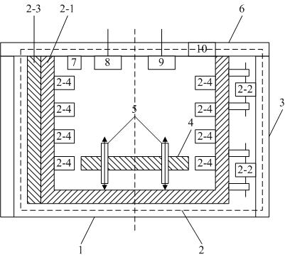
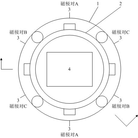
[0104] The MEMS palladium alloy probe testing device under the present embodiment, the structure schematic diagram is as follows figure 1 shown. The MEMS palladium alloy probe testing device comprises a barrel-shaped housing 1, a disturbance structure 2 arranged on the inner wall of the barrel-shaped housing 1, an electromagnetic pole 3 arranged on the outer wall of the barrel-shaped housing 1, and arranged horizontally in the barrel-shaped housing 1 Placed reference test platform 4, a symmetrical bending test structure 5 positioned above the reference test platform 4, a sealing cover 6 arranged above the barrel-shaped housing 1 and a sensor 7 installed on the sealing cover 6, a sprayer 8, a heater 9 and fan 10;

[0105] The disturbance structure 2 includes a disturbance body 2-1 with a circular cross section, a roller 2-2 and a tooth structure 2-3 dispo...

specific Embodiment approach 2

[0112] The following is a specific embodiment of the MEMS palladium alloy probe testing device of the present invention.

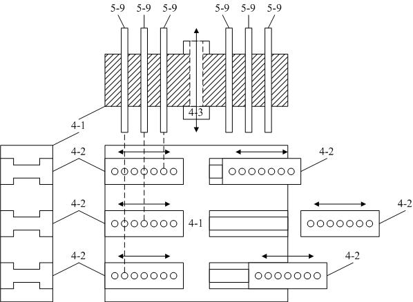
[0113] The MEMS palladium alloy probe test device under the present embodiment, on the basis of the specific embodiment one, further defines that the benchmark test platform includes a main board 4-1 and a plurality of sliders 4-2, and the main board 4-1 is provided with There are gaps from both sides to the center of symmetry, the cross-sectional shape of the gap is "I" shape, a slider 4-2 is inserted in the gap, and a plurality of vertical shafts are equally spaced on the slider 4-2 A circular through hole in a straight direction, the through hole can be equipped with a lifting structure 5-9, such as image 3 Shown; The material of described main board 4-1 and slide block 4-2 is different, specifically as follows:

[0114] First, the speed at which the volume of the material of the main board 4-1 increases with the increase of temperature is lower than ...

specific Embodiment approach 3

[0120] The following is a specific implementation of the benchmark test platform in the MEMS palladium alloy probe test device of the present invention.

[0121] The benchmark test platform under the present embodiment includes a main board 4-1 and a plurality of sliders 4-2, the main board 4-1 is provided with a gap from both sides to the symmetrical center direction, and the cross-sectional shape of the gap is "I" shape, a slider 4-2 is inserted in the gap, and a plurality of circular through holes in the vertical direction are equally spaced on the slider 4-2, and the through holes can be installed with a lifting structure 5- 9, such as image 3 Shown; The material of described main board 4-1 and slide block 4-2 is different, specifically as follows:

[0122] First, the speed at which the volume of the material of the main board 4-1 increases with the increase of temperature is lower than that of the material of the slider 4-2 with the increase of temperature. Before testi...


PUM


Abstract

A MEMS probe single-axis symmetrical bending test structure and its pitching arm of the present invention belong to the field of IC manufacturing industry; the structure is sequentially provided with a first main shaft, a first shaft adapter, a cross adapter, and a first shaft from top to bottom. The two-axis adapter and the second main shaft, the first main shaft, the first shaft adapter, the cross adapter, the second shaft adapter and the second main shaft are vertically symmetrical about the cross adapter; the cross adapter A rotatable left pitching arm is installed coaxially on the left end of the cross adapter, and a rotatable right pitching arm is coaxially installed on the right end of the cross adapter; pull rods are installed on the outer ends of the left and right pitching arms to lift The lower ends of the pull rods are connected to the top of the lifting structure; the lifting structure moves up and down; this structure can simultaneously test the tensile performance and bending performance of multiple probe cards of different sizes; since only one motor is needed, Therefore, the crowded situation of multiple driving devices in a small size is avoided, and the heat dissipation problem of the MEMS device is solved.

Description

technical field [0001] The invention discloses a MEMS probe single-axis symmetrical bending test structure and its pitch arm, which belong to the field of IC manufacturing industry, and specifically relate to a device, method and related key technologies for performance testing of palladium alloy probes in MEMS probe cards. Background technique [0002] The probe card is a very important technology in the chip manufacturing process. Before the chip is packaged, the probes on the probe card directly contact the pads or bumps on the chip to lead out the chip signal, and then cooperate with peripheral testing instruments and Software control realizes automatic measurement, and then screens out defective products to ensure product yield. [0003] With the development of micro-electromechanical system (MEMS) technology, the size of the chip is getting smaller and smaller, reaching the order of millimeters, and the degree of integration inside the chip is getting higher and higher...

Claims


Application Information

Patent Timeline
Patent Type & Authority Patents(China)
IPC IPC(8): G01N3/02G01N3/08G01N3/20
CPCG01N3/02G01N3/08G01N3/20G01N2203/0017G01N2203/0023G01N2203/005
Inventor 于海超周明赵梁玉刘明星
Owner MAXONE SEMICON CO LTD
Why Eureka
Try Eureka