
Hollow fiber membrane spinneret device

A technology of spinning device and fiber membrane, which is applied in the field of spinning device of hollow fiber membrane, can solve the problems of inability to adjust and optimize the production process, waste of raw materials and labor costs, difficult realization of porous consistency requirements, etc., and achieves convenient multi-head expansion, The effect of improving production stability and reducing the difficulty of production and assembly

Pending Publication Date: 2020-08-07
SHANGHAI TRUSTECH TECH DEV CO LTD
View PDF6 Cites 0 Cited by
  • Summary
  • Abstract
  • Description
  • Claims
  • Application Information

AI Technical Summary

Problems solved by technology

[0009] 1. When multi-head expansion is performed on multiple independent spinnerets with multiple efficiency, the design and production requirements for the flow channel module are very high, and the consistency requirements of the holes are difficult to achieve, and the qualified rate of the product will fluctuate greatly due to the influence of production parameters. Large, low qualified rate; after the hollow fiber membranes with poor consistency are assembled into a membrane group, the water filtration area of ​​the membranes per unit volume will be greatly reduced, and the flux will not meet the design standards; in addition, the ring design The feeding trough may cause residual agglomeration of the feed liquid, which is not easy to clean and will affect the repeated use of the product
[0010] 2. Inconvenient cleaning and maintenance, waste of downtime, waste of a lot of raw materials and labor costs; there are abnormalities in the production line, often need to stop for maintenance
[0011] 3. It is not possible to individually control each outlet hole, so that the production process cannot be adjusted and optimized, etc.

Method used


Image

  • Hollow fiber membrane spinneret device
  • Hollow fiber membrane spinneret device
  • Hollow fiber membrane spinneret device

Examples


Embodiment Construction

[0057] The following will clearly and completely describe the technical solutions in the embodiments of the present invention with reference to the accompanying drawings in the embodiments of the present invention. Obviously, the described embodiments are only some, not all, embodiments of the present invention.

[0058] In describing the present invention, it should be understood that the terms "upper", "lower", "front", "rear", "left", "right", "top", "bottom", "inner", " The orientation or positional relationship indicated by "outside", etc. is based on the orientation or positional relationship shown in the drawings, and is only for the convenience of describing the present invention and simplifying the description, rather than indicating or implying that the referred device or element must have a specific orientation, so as to Specific orientation configurations and operations, therefore, are not to be construed as limitations on the invention.

[0059] refer to Figure ...


PUM


Abstract

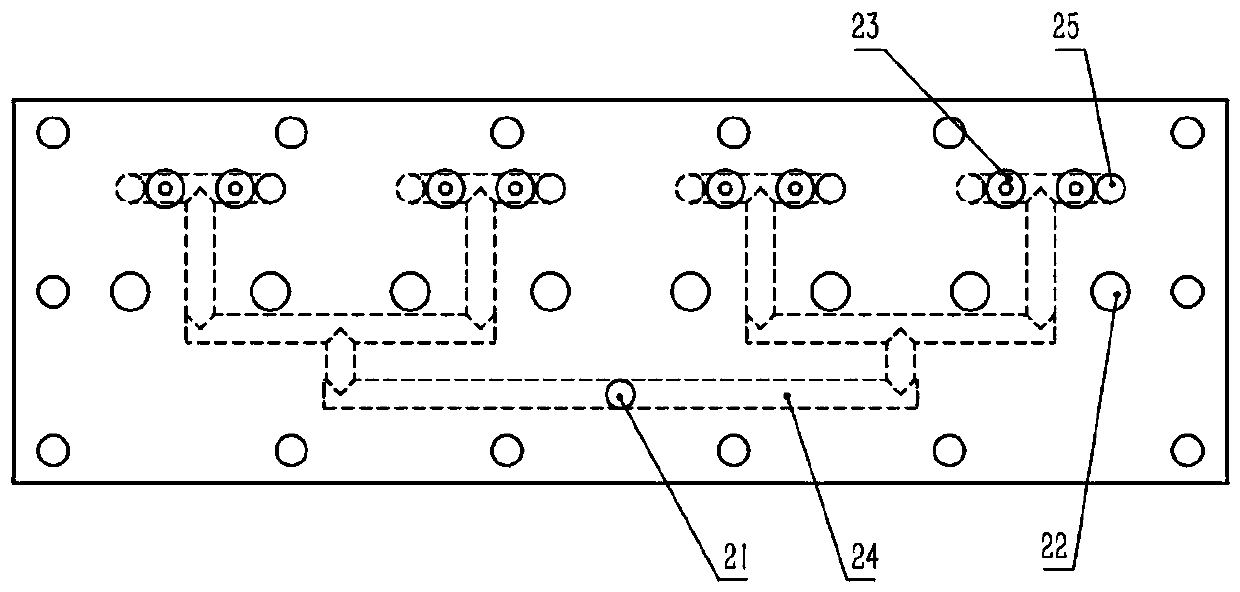
The invention discloses a hollow fiber membrane spinneret device. The device comprises a flow guide module, core liquid flow control modules, material liquid flow control modules and independent spinneret bodies, wherein the flow guide module comprises a flow guide base, a core liquid flow guide plate and a material liquid flow guide plate, the independent spinneret bodies penetrate through mounting holes formed in the material liquid flow guide plate and core liquid cavities formed in the core liquid material guide plate, and the independent spinneret bodies are coaxial with the mounting holes and the core liquid cavities. According to the device, the structure is simple, the operation is convenient, each spinneret hole can be independently controlled, core liquid and material liquid flowwell, the production assembly difficulty is reduced, maintenance and replacement of single spinneret can be realized when a problem occurs, the maintenance time and material cost are reduced, the multi-head expansion is very convenient, the modular, customized, flexible production of products of different specifications is realized on the same equipment at the same time, and breakthrough improvement in production efficiency is promoted.

Description

technical field [0001] The invention relates to the technical field of hollow fiber membranes, in particular to a hollow fiber membrane spinning device. Background technique [0002] Hollow fiber membrane is the core component of equipment in the fields of water treatment, hemodialysis, and gas separation. It is an important new material used in microfiltration membranes, nanofiltration membranes, and ultrafiltration membranes. Separation and other fields have gradually been more and more widely used. With the improvement of the quality and performance requirements of hollow fiber membranes and the increase of demand, the existing domestic production processes and equipment are becoming more and more difficult to meet the production needs, and most of them rely on imports. How to produce high-performance hollow fiber membranes, improve production efficiency, and reduce production costs has become one of the hottest and most critical issues in the field of research on hollow...

Claims


Application Information

Patent Timeline
Patent Type & Authority Applications(China)
IPC IPC(8): D01D5/24D01D4/06
CPCD01D5/24D01D4/06
Inventor 王立峰伍春兰舒建存
Owner SHANGHAI TRUSTECH TECH DEV CO LTD
Learn More