
Vibration forming platform for casting mold

A vibration forming and platform technology, applied in casting forming equipment, casting molds, casting mold components, etc., can solve problems such as incomplete vibration, achieve smooth casting surface, improve casting quality, and prevent excessive cooling effects.

Active Publication Date: 2020-08-07
安徽省安工机械制造有限公司
View PDF5 Cites 5 Cited by
  • Summary
  • Abstract
  • Description
  • Claims
  • Application Information

AI Technical Summary

Problems solved by technology

Most of the existing vibration pouring platforms use vibration motor as the vibration source. The disadvantage of the vibration motor is that it can only vibrate from one direction, resulting in incomplete vibration. Therefore, we propose a new type of casting mold vibration forming platform.

Method used


Image

  • Vibration forming platform for casting mold
  • Vibration forming platform for casting mold
  • Vibration forming platform for casting mold

Examples


Embodiment 1

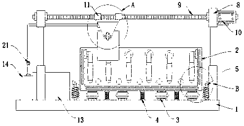
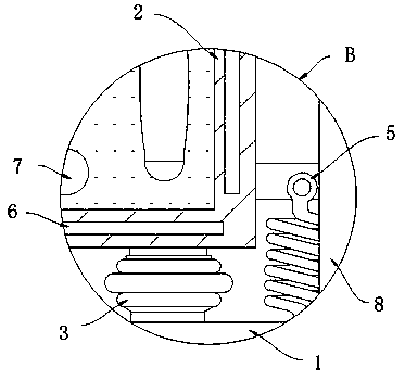
[0024] refer to Figure 1-2 , a casting mold vibration molding platform, including a platform base 1, the upper surface of the platform base 1 is provided with a vibration box 2, the inside of the vibration box 2 is filled with a sand-water mixture, and the sand-water ratio of the sand-water mixture is 6:4 , The specifications of the sand in the sand-water mixture are all fine sand passing through a 50-mesh sieve.

[0025] A plurality of air springs 3 and support springs 4 are fixedly connected between the vibration box 2 and the platform base 1, and a tension spring 5 is fixedly connected to the bottom end of the outer surface of the vibration box 2, and the bottom end of the tension spring 5 is fixedly connected to the platform base 1, A heating plate 6 is arranged inside the box body of the vibration box 2 , and a plurality of vibrators 7 are arranged on the inner side wall and the inner bottom wall of the vibration box 2 .

[0026] In this embodiment, by arranging a plura...

Embodiment 2

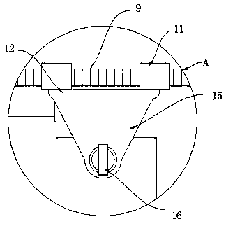
[0028] refer to Figure 3-5 , different from Embodiment 1, the surface of the platform base 1 is provided with a lifting frame 8, the cross bar of the lifting frame 8 is made of a screw rod 9, and the lifting frame 8 is a rectangular frame composed of an electric telescopic rod, a longitudinal rod and a screw rod 9 Structure, the four electric telescopic rods use the PLC controller to control the lifting synchronously.

[0029] The screw mandrel 9 extends to the right side of the lifting frame 8 and is fixedly connected with a servo motor 10. The surface of the screw mandrel 9 is threadedly connected with a screw nut block 11, and the lower surface of the screw mandrel nut block 11 is connected with the same horizontal block 12. The lower surface of the block 12 is fixedly connected with a mold clamping assembly, and the clamping assembly for clamping the mold includes a clamping lower opening concave block 15 fixedly connected to the lower surface of the cross block 12, the f...


PUM


Abstract

The invention discloses a vibration forming platform for a casting mold. The platform comprises a platform base. A vibration box is arranged on the upper surface of the platform base, the vibration box is internally filled with a sand-water mixed solution, a plurality of air springs and supporting springs are fixedly connected between the vibration box and the platform base, the bottom end of theouter surface of the vibration box is fixedly connected to a tension spring, and the bottom of the tension spring is fixedly connected to the platform base. According to the vibration forming platformfor the casting mold, by arranging the inner wall of the vibration box and a plurality of vibrators on the inner bottom wall, a mold immersed into the sand-water mixed solution receives a vibration force transferred by the sand-water mixed solution as a medium all around, so that vibration is more thorough and air bubbles in the mold can collide and are discharged from a sprue gate of the mold. By arranging a heating sheet, the sand-water mixed solution in the mold is heated to prevent molten iron in the mold from being cooled quickly, so that the surface of a cooled and formed casting is smoother, and the casting quality is improved.

Description

technical field [0001] The invention relates to the technical field of casting forming equipment, in particular to a casting mold vibration forming platform. Background technique [0002] In lost foam casting, in general, there are many factors that affect the quality of the finished casting, such as the structure, shape, size of the lost foam casting itself, and the influence of the molding and pouring process in the casting process. Among them, after many castings are poured and formed, there are many pores and cracks on the surface. A large part of the reason is that the molten iron mold has been in a static state after pouring, resulting in internal air bubbles that cannot be released, pouring is incomplete, and pores appear. [0003] Therefore, after injecting the molten iron, we need to vibrate the mold to a certain extent to release the air bubbles inside, so that the molten iron can penetrate into every corner of the mold. Most of the existing vibration pouring plat...

Claims


Application Information

Patent Timeline
Patent Type & Authority Applications(China)
IPC IPC(8): B22D27/08B22C9/04
CPCB22C9/04B22D27/08
Inventor 费昭鹤
Owner 安徽省安工机械制造有限公司
Learn More