
Filtering device for air purification equipment

A technology of air purification equipment and filter devices, which is applied in the direction of combined devices, dispersed particle filtration, transportation and packaging, etc., which can solve the problems of high maintenance frequency, unfavorable use, and increased maintenance costs, so as to reduce maintenance frequency, reduce moisture, and maintain Easy to clean up

Pending Publication Date: 2020-08-07
长兴诚得环保设备有限公司
View PDF6 Cites 3 Cited by
  • Summary
  • Abstract
  • Description
  • Claims
  • Application Information

AI Technical Summary

Problems solved by technology

[0003] The existing filter device for air purification equipment has a simple structure, and only needs to filter the filter. After the filter is used for a long period of time, the filter needs to be disassembled and cleaned. The maintenance frequency is high, which increases the maintenance cost and is not conducive to use.

Method used


Image

  • Filtering device for air purification equipment
  • Filtering device for air purification equipment
  • Filtering device for air purification equipment

Examples


Embodiment 1

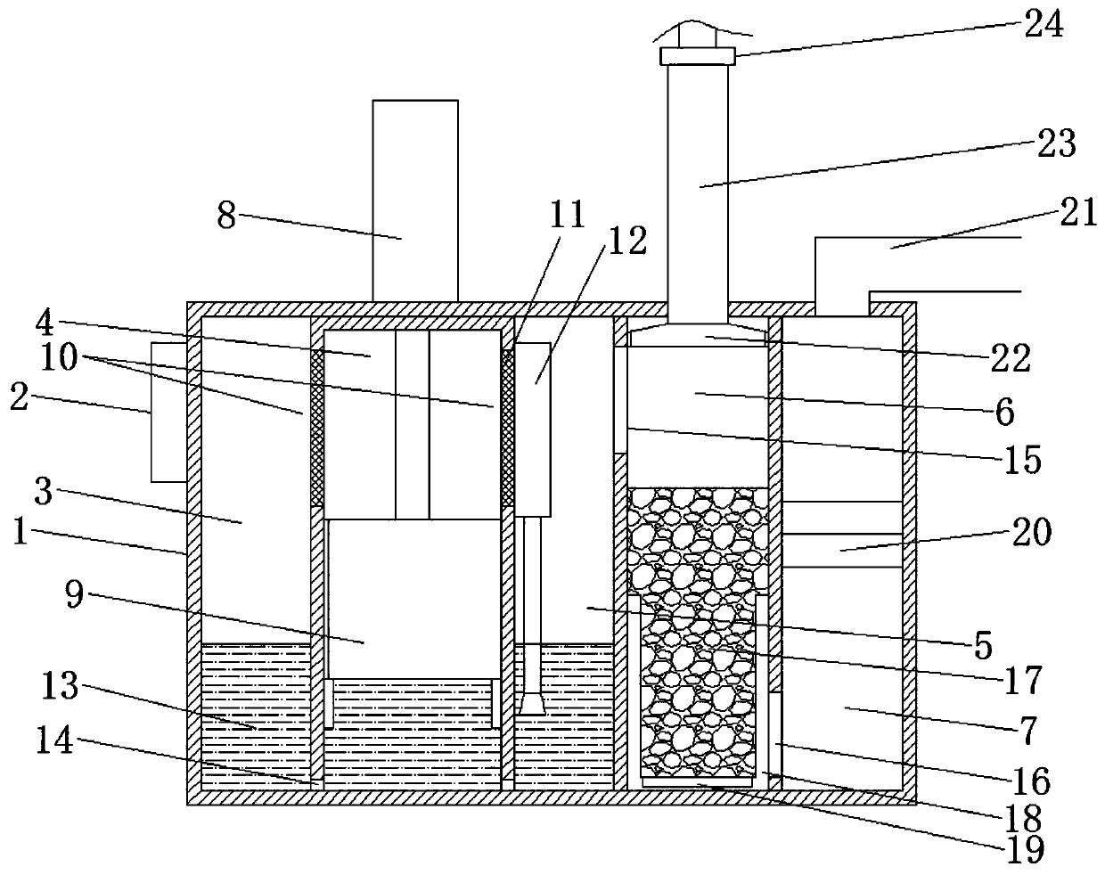
[0022] Please refer to the figure, in an embodiment of the present invention, a filter device for air purification equipment includes a housing 1, a blower 2, a cylinder 8 and an air outlet pipe 21; the housing 1 is separated from left to right by a partition plate into The first water chamber 3 , the extrusion cleaning chamber 4 , the second water chamber 5 , the drying chamber 6 and the fine filter chamber 7 .

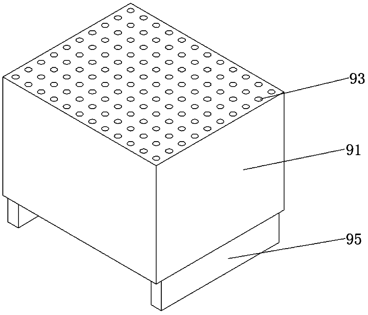
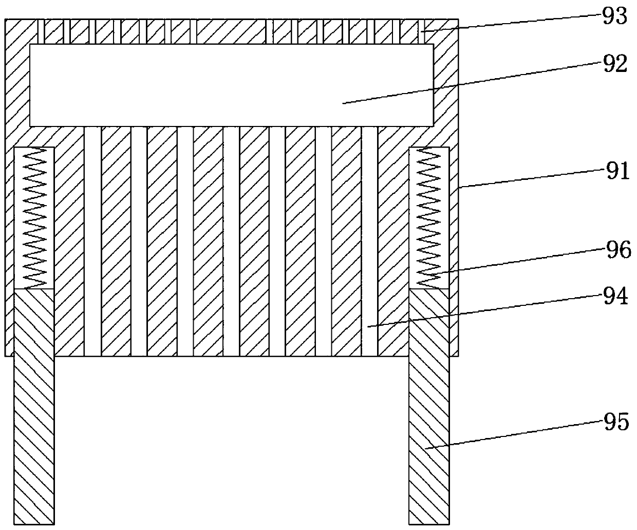
[0023] The side wall of the first water chamber 3 is communicated with a blower 2 to send the external air into the shell 1; the bottom between the first water chamber 3 and the extrusion cleaning chamber 4, the extrusion cleaning chamber 4 and the The bottoms between the second water chambers 5 are communicated through several openings 14. Cleaning water 13 is filled in the first water chamber 3, the extrusion cleaning chamber 4, and the second water chamber 5. The first water chamber 3, extrusion cleaning The cavity 4 and the second water cavity 5 are filled with c...

Embodiment 2

[0029] On the basis of embodiment 1, the bottom in the described drying chamber 6 is fixedly installed with a heating element 19 for heating above, and the heating element 19 heats the pipe, and the heating oil is passed inside to increase the temperature in the drying chamber 6. When cleaning, the drying chamber 6 is heated, and the moisture in the drying packing 17 is evaporated and taken away. On the top of the drying chamber 6, a dehumidification wind cover 22 is installed, and the dehumidification wind cover 22 is slidably connected on the inner wall of the drying chamber 6. Move down to the dry filler 17, so that the generated water vapor directly enters the dehumidification wind cover 22, and the dehumidification wind cover 22 is connected with a dehumidification pipe 23, and a valve 24 is installed on the dehumidification pipe 23. When cleaning, open the valve 24 to discharge water vapor . The dry packing 17 in the drying chamber 6 is maintained to prolong its service ...


PUM


Abstract

The invention relates to the field of environmental protection, and particularly discloses a filtering device for air purification equipment. The filtering device comprises a shell, an air feeder, anair cylinder and an air outlet pipe, wherein the interior of the shell is sequentially divided into a first water cavity, an extrusion cleaning cavity, a second water cavity, a drying cavity and a fine filtering cavity from left to right through partition plates; and a filter screen is fixedly embedded in a ventilation opening; an extrusion piston mechanism ascending and descending in a vertical direction is arranged in the extrusion cleaning cavity, a plurality of spraying holes penetrating through the top of a piston body communicate with the top of the cavity, and a plurality of water inletholes downwards penetrating through the bottom of the piston body communicate with the bottom of the cavity. In the cleaning process of the filtering device, only an air cylinder needs to be started,and the internal extrusion piston mechanism is driven by the air cylinder to move, internal filtering water serves as cleaning water to wash away dust on the filter screen, reduce the dust on the filter screen, clean the filter screen and guarantee air passing performance.

Description

technical field [0001] The invention relates to the field of environmental protection, in particular to a filter device for air purification equipment. Background technique [0002] People have always thought that the most serious air pollution is outdoors, but in fact, the indoor environment of factories, offices, living rooms, restaurants, theaters, Internet clubs, dance halls and other buildings has a much greater impact on people's health than outdoors. About 80% of the time in a lifetime is spent indoors. Therefore, the quality of the indoor environment directly affects human health. From the reality, the indoor air quality is far worse than the outdoor atmospheric environment. Therefore, we need to use air The purification filter device is used to filter and purify the air in the room. [0003] The existing filter device for air purification equipment has a simple structure, and only needs to filter the filter. After the filter is used for a long period of time, the f...

Claims


Application Information

Patent Timeline
Patent Type & Authority Applications(China)
IPC IPC(8): B01D50/00B01D53/26B01D46/00B01D46/12
CPCB01D46/12B01D53/261B01D46/70B01D50/60
Inventor 许海学
Owner 长兴诚得环保设备有限公司
Learn More