Electrode and fabrication method, electrode element and nonaqueous electrolytic storage element
An electrode element and electrode technology, applied in the field of non-aqueous electrolyte storage elements, can solve problems such as difficult short circuit, and achieve the effect of suppressing thermal runaway reaction
- Summary
- Abstract
- Description
- Claims
- Application Information
AI Technical Summary
Problems solved by technology
Method used
Image
Examples
no. 1 approach
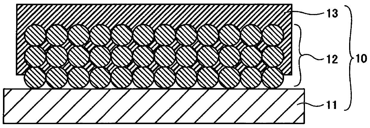
[0035] figure 1 A cross-sectional view for explaining the negative electrode used in the non-aqueous electrolyte storage element according to the first embodiment. refer to figure 1 The negative electrode 10 is configured to include a negative electrode substrate 11 , a negative electrode mixture layer 12 formed on the negative electrode substrate 11 , and a porous insulating layer 13 formed on the negative electrode mixture layer 12 . The shape of the negative electrode 10 is not particularly specified and may be appropriately selected according to purposes; for example, the shape of the negative electrode 10 may be a flat plate or the like.
[0036] In the negative electrode 10 , at least a part of the porous insulating layer 13 exists inside the negative electrode mixture layer 12 and is integrated (integrated) with the surface of the active material constituting the negative electrode mixture layer 12 . Note that "integrated with the surface" in this case is not a membra...
Embodiment 1
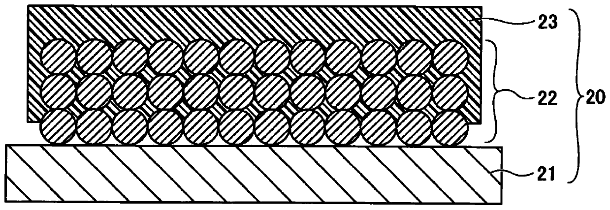
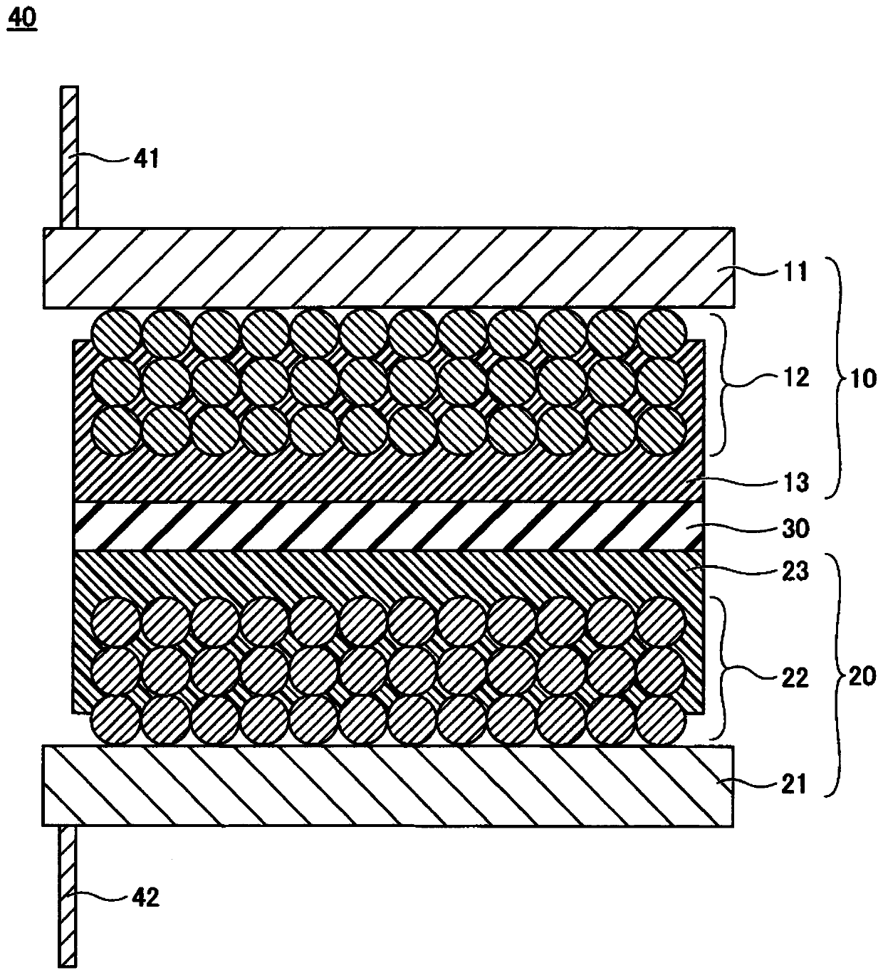
[0127] The negative electrode 10, the positive electrode 20, the electrode element 40, and the nonaqueous electrolyte power storage element 1 were prepared as follows.
[0128] ink preparation
[0129] As the ink for forming the insulating layer, the following solutions were prepared:
[0130] - Tricyclodecane dimethanol diacrylate (Daicel-Ornix Corporation): 49 parts by mass
[0131] - Dipropylene glycol monomethyl ether (manufactured by Kanto Chemical Co., Ltd.): 50 parts by mass
[0132] -Irgacure 184 (manufactured by BASF): 1 part by mass Preparation of negative electrode 10
[0133] 97 parts by mass of graphite particles (average particle size: 10 μm) as a negative active material, 1 part by mass of cellulose as a thickener, and 2 parts by mass of acrylic resin as a binder were uniformly dispersed in water to prepare a negative active material Dispersions. The dispersion was applied to a copper foil having a thickness of 8 μm as the negative electrode substrate 11 , a...
Embodiment 2
[0157] ink preparation
[0158] As the ink for forming the insulating layer, the following solutions were prepared:
[0159] - Tricyclodecane dimethanol diacrylate (Daicel-Ornix Corporation): 29 parts by mass
[0160] - Dipropylene glycol monomethyl ether (manufactured by Kanto Chemical Co., Ltd.): 70 parts by mass
[0161] - Irgacure 184 (manufactured by BASF): 1 part by mass
[0162] After preparing the ink, a nonaqueous electrolyte power storage element 1 was prepared in the same manner as described in Example 1.
[0163] As a result of the SEM observation, it was found that the insulating layers 13A and 23A obtained in Example 2 were observed to have pores having a size of about 0.1-1.0 μm. That is, the results of SEM observation indicated that the prepared insulating layers 13A and 23A were porous insulating layers.
[0164] Next, a viscosity measurement test and an impedance measurement test were performed in the same manner as in Example 1 on the ink for forming an ...
PUM
| Property | Measurement | Unit |
|---|---|---|
| particle size | aaaaa | aaaaa |
| thickness | aaaaa | aaaaa |
| thickness | aaaaa | aaaaa |
Abstract
Description
Claims
Application Information
 - R&D
- Intellectual Property
- Life Sciences
- Materials
- Tech Scout
- Unparalleled Data Quality
- Higher Quality Content
- 60% Fewer Hallucinations
Browse by: Latest US Patents, China's latest patents, Technical Efficacy Thesaurus, Application Domain, Technology Topic, Popular Technical Reports.
© 2025 PatSnap. All rights reserved.Legal|Privacy policy|Modern Slavery Act Transparency Statement|Sitemap|About US| Contact US: help@patsnap.com


