Engine rapid combustion device suitable for low-evaporation characteristic fuel

A combustion device and engine technology, which is applied in the direction of combustion engines, internal combustion piston engines, machines/engines, etc., can solve the problem of insignificant improvement in the combustion speed of large-bore engines, increased weight and volume costs of ignition coils, and aggravated spark plug electrode wear, etc. problems, to achieve the effect of improving ignition stability and reliability, speeding up flame propagation, and speeding up combustion flame propagation

Pending Publication Date: 2020-08-04
天津内燃机研究所(天津摩托车技术中心)
View PDF0 Cites 2 Cited by
  • Summary
  • Abstract
  • Description
  • Claims
  • Application Information

AI Technical Summary

Problems solved by technology

[0002] Due to its own physical and chemical properties, fuels with low evaporation characteristics have characteristics such as low saturated vapor pressure and slow evaporation rate. However, when they are applied to ignition piston engines, they will generally cause poor mixture formation quality, unstable combustion process, and flame propagation. Slower speed and other problems will cause the engine to be difficult to start cold, easy to knock, and insufficient power output.
The traditional spark plug ignition method only relies on increasing the ignition energy to achieve the purpose of improving ignition reliability and stability, but the increase in ignition energy will also increase the wear of the spark plug electrode, and the weight, volume and cost of the ignition coil will increase. At the same time, traditional spark plug ignition has no obvious effect on increasing the combustion speed of large-bore engines by increasing the ignition energy. Therefore, there are large technical barriers to speeding up the combustion speed of low-evaporation fuel engines and improving combustion stability.

Method used

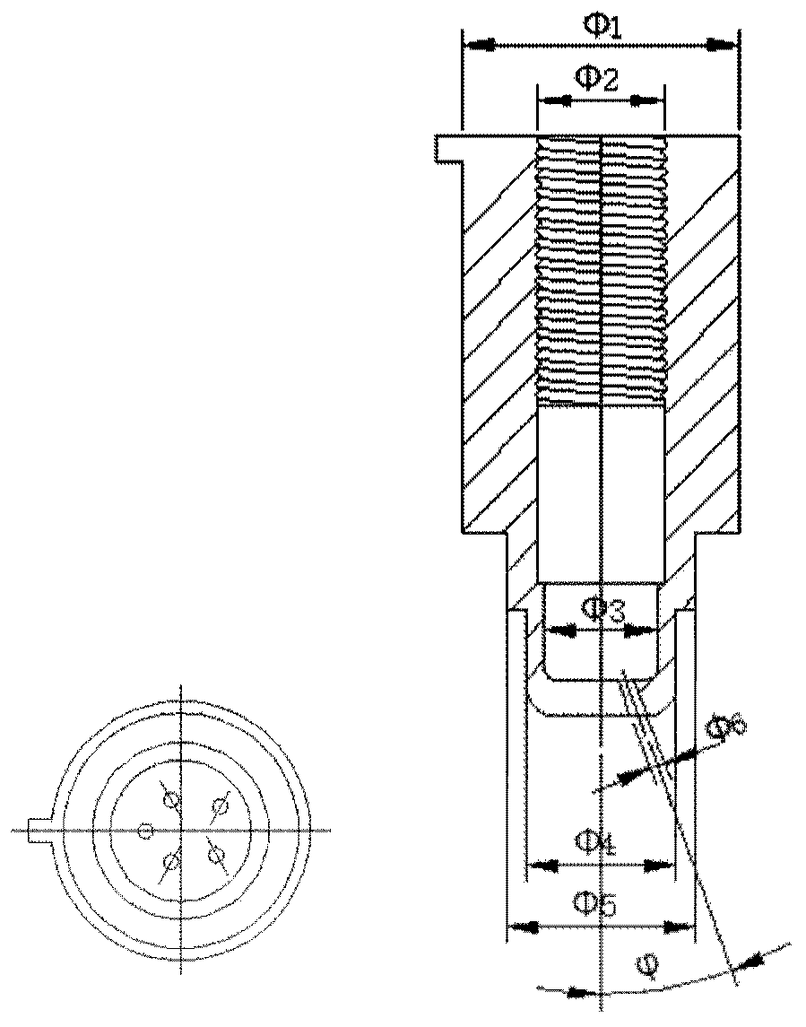

Image

  • Engine rapid combustion device suitable for low-evaporation characteristic fuel
  • Engine rapid combustion device suitable for low-evaporation characteristic fuel
  • Engine rapid combustion device suitable for low-evaporation characteristic fuel

Examples


Embodiment Construction

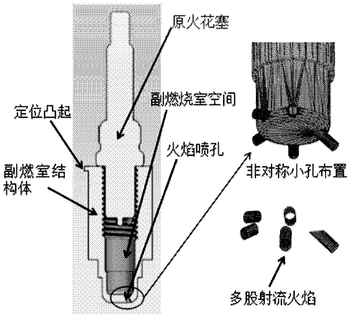
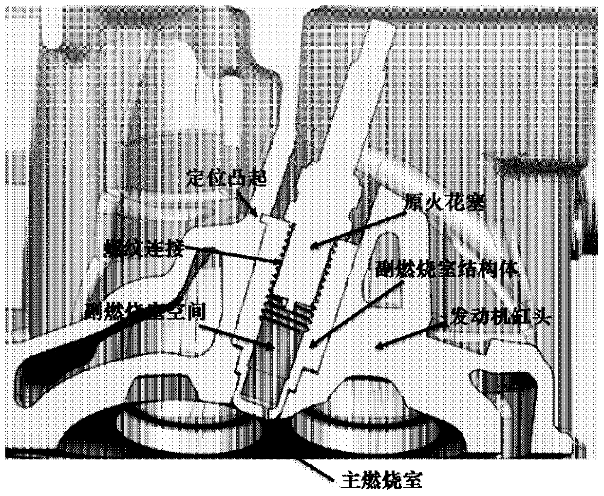
[0026] In order to improve the combustion speed and combustion stability of engines with low-evaporation-characteristic fuels, promote the rapid combustion of large-bore engines, and then improve their workability, a scheme for rapid combustion devices for engines with low-evaporation-characteristic fuels is proposed. The basic principle is: an auxiliary combustion chamber is formed at the original spark plug, and the auxiliary combustion chamber is positioned and connected with the engine through the positioning protrusion and the tablet pressing device. The initial flame is generated by the discharge of the original spark plug in the auxiliary combustion chamber, and then the flame is generated in the auxiliary combustion chamber. And develop rapidly, and then generate multiple jet flames through multiple flame nozzles connecting the auxiliary combustion chamber and the main combustion chamber, and the multiple jet flames are injected into the main combustion chamber at the sa...


PUM


Abstract

The invention relates to an engine combustion device. The engine combustion device comprises a main combustion chamber, a spark plug, an auxiliary combustion chamber and flame spray holes, wherein initial flames are generated in the auxiliary combustion chamber through discharging of the spark plug, then the flames are generated in the auxiliary combustion chamber and develop rapidly, then multiple jet flames are generated through the plurality of spray holes used for connecting the auxiliary combustion chamber with the main combustion chamber, the multiple jet flames are jetted into the maincombustion chamber at the same time and are equivalent to a high-energy multi-core ignition source of the main combustion chamber, and mixed gas in the main combustion chamber is ignited by multiple large-area flames at the same time. According to the engine combustion device, the combustion speed of the mixed gas is increased, the ignition stability and reliability are improved, and the knockingphenomenon can be effectively restrained.

Description

technical field [0001] The invention relates to the technical field of energy utilization, in particular to an engine rapid combustion device suitable for fuels with low evaporation characteristics. Background technique [0002] Due to its own physical and chemical properties, fuels with low evaporation characteristics have characteristics such as low saturated vapor pressure and slow evaporation rate. However, when they are applied to ignition piston engines, they will generally cause poor mixture formation quality, unstable combustion process, and flame propagation. Slower speed and other problems will cause the engine to be difficult to start cold, easy to knock, and insufficient power output. The traditional spark plug ignition method only relies on increasing the ignition energy to achieve the purpose of improving ignition reliability and stability, but the increase in ignition energy will also increase the wear of the spark plug electrode, and the weight, volume and co...

Claims


Application Information

Patent Timeline
Patent Type & Authority Applications(China)
IPC IPC(8): F02B19/12F02B19/16
CPCF02B19/12F02B19/16Y02T10/12
Inventor 胡春明刘娜宋玺娟杜春媛张振东田梦园
Owner 天津内燃机研究所(天津摩托车技术中心)
Why Eureka
Try Eureka