Blade tip coating of a blade of a gas turbine engine

A gas turbine and engine technology, applied in the direction of engine components, machines/engines, blade support components, etc., can solve problems such as damage and instability of other parts, and achieve the effects of improving functionality, improving reliability, and extending service life

Inactive Publication Date: 2021-06-22
SHANDONG JIAOTONG UNIV
View PDF0 Cites 0 Cited by
  • Summary
  • Abstract
  • Description
  • Claims
  • Application Information

AI Technical Summary

Problems solved by technology

[0003] In the blade, the more complicated environment is the tip part. Since the tip part needs to be directly sealed and connected with the static parts, it is bound to produce certain wear and tear. However, if the wear is too severe, it will damage other parts and even directly cause unstable

Method used


Image

  • Blade tip coating of a blade of a gas turbine engine
  • Blade tip coating of a blade of a gas turbine engine

Examples


Embodiment Construction

[0018] In order to clearly illustrate the technical features of the present solution, the present application will be described in detail below through specific implementation modes.

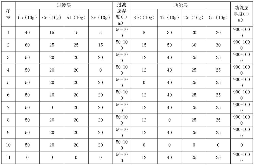
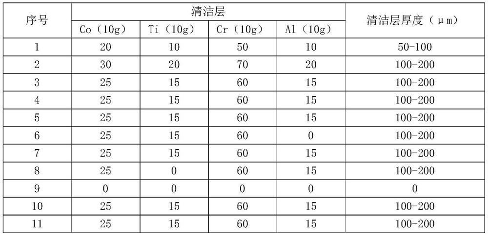
[0019] In the embodiment, prepare the same board as the blade tip, and then configure the raw materials of the transition layer, functional layer and cleaning layer:

[0020] S1. First, carry out surface friction treatment on the plate;

[0021] S2. Ball mill 200-500 meshes of Co, Cr, Al, Zr under the protection of an inert gas for no less than 3 hours, and then put it into a plasma spraying device to spray the tip of the blade under the protection of an inert gas, and the ionized gas is hydrogen;

[0022] S3. Ball mill 200-500 meshes of Co, Cr, and Ti under the protection of an inert gas for no less than 3 hours, then put 200-500 meshes of SiC, and then put it into a plasma spraying device to protect the tip of the blade under the protection of an inert gas. Spraying is carried out on the tran...


PUM

PropertyMeasurementUnit
thicknessaaaaaaaaaa
thicknessaaaaaaaaaa
thicknessaaaaaaaaaa

Abstract

A blade tip coating of a blade of a gas turbine engine, comprising a transition layer for connecting with the blade, the transition layer is provided with a functional layer on the side away from the blade, and the outer side of the functional layer is provided with a cleaning layer, so the The cleaning layer includes a substantially smooth plane, and a plurality of cleaning protrusions are evenly distributed on the plane. The present application adopts a multi-layer structure so that different layers can realize different structures and obtain different functions, thereby improving the overall functionality of the coating and greatly improving its reliability.

Description

technical field [0001] The present application relates to a tip coating of a blade of a gas turbine engine. Background technique [0002] In a gas turbine engine, the main moving part is the turbine, and the turbine itself mainly transmits corresponding energy through the blades, and is in close contact with the static parts of the outside world. Therefore, the nature of the turbine itself almost determines the quality of the gas turbine engine. In order to enhance the performance of the turbine, there are many methods in the industry, which can be roughly divided into the optimization of its own structure, materials and coating. [0003] In the blade, the more complicated environment is the tip part. Since the tip part needs to be directly sealed and connected with the static parts, it is bound to produce certain wear and tear. However, if the wear is too severe, it will damage other parts and even directly cause Unsteady. Contents of the invention [0004] In order to ...

Claims


Application Information

Patent Timeline
Patent Type & Authority Patents(China)
IPC IPC(8): F01D5/28C23C4/08C23C4/06C23C4/134C23C4/137C22C30/00C22C19/07C22C27/06B22F1/00B22F9/04
CPCF01D5/28F01D5/284F01D5/288C23C4/08C23C4/06C23C4/134C23C4/137C22C30/00C22C19/07C22C19/007C22C14/00C22C32/0063C22C27/06B22F9/04B22F2009/043B22F1/052
Inventor 杨君张庆林韩广德王健周学升李延骁高岩飞刘永辉郭峻宇
Owner SHANDONG JIAOTONG UNIV
Why Eureka
Try Eureka