Improved peritoneal dialysis device

An improved, peritoneal dialysis technology, applied in the field of medical appliances, can solve the problems of no volume scale of the liquid bag, unfavorable specimen collection, insufficient liquid discharge, etc., to improve the accuracy and sterility, and to facilitate the observation of the liquid output. , functional and practical effects

Pending Publication Date: 2020-08-04
徐媛
View PDF0 Cites 1 Cited by
  • Summary
  • Abstract
  • Description
  • Claims
  • Application Information

AI Technical Summary

Problems solved by technology

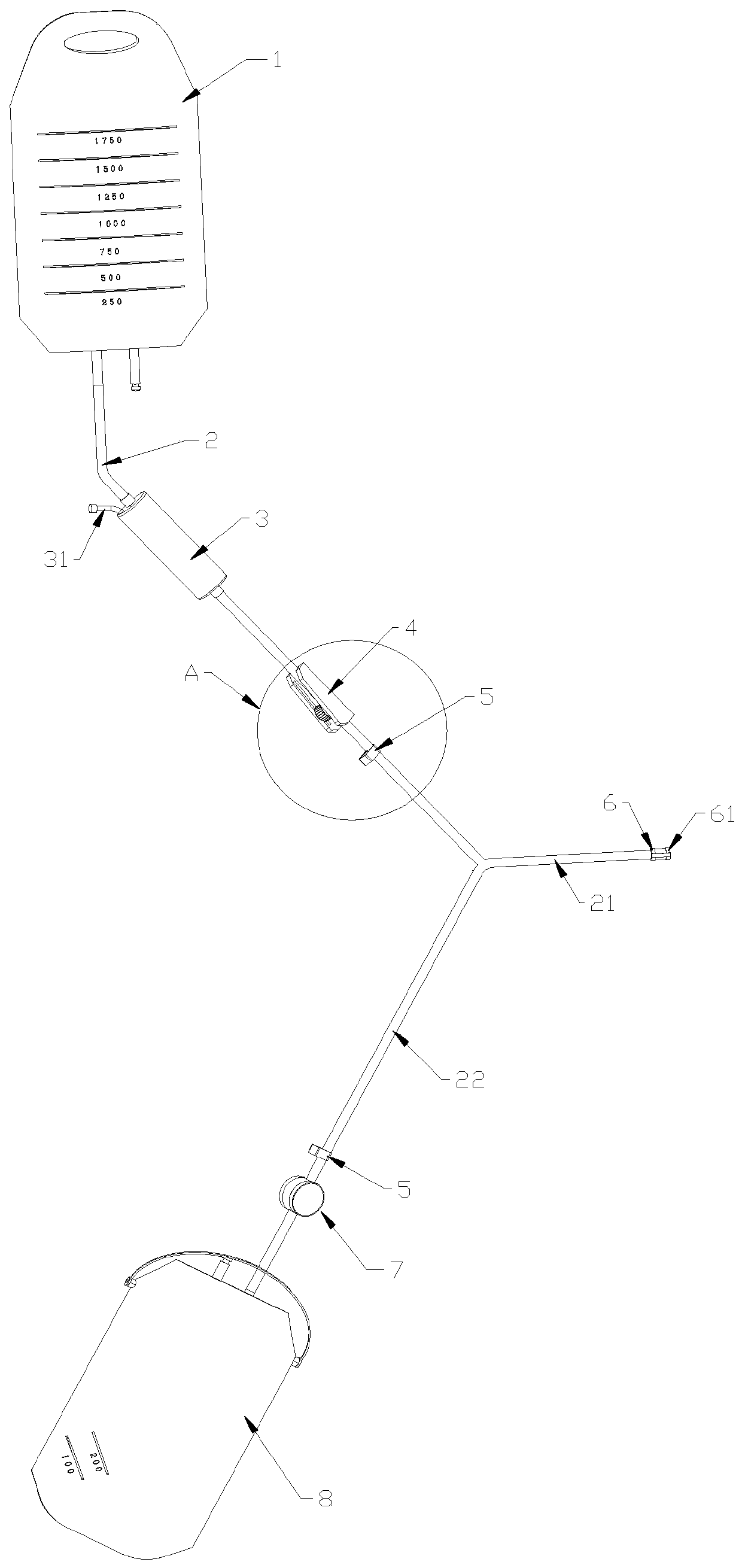
Existing peritoneal dialysis devices have non-integrated peritoneal dialysis devices, which cannot control the exhaust speed and liquid intake speed before liquid intake, which is not conducive to specimen retention. The fluid bag has no capacity scale, insufficient liquid discharge, and patients cannot control liquid intake. Exhaust speed and liquid inflow speed before, resulting in a waste of peritoneal dialysis fluid, the waste fluid bag section does not retain the specimen port, which is not conducive to specimen collection, the peritoneal dialysis fluid bag has no capacity scale, and the infusion and extraction capacity cannot be clearly seen. It is impossible to accurately judge the amount of inflow, and for patients undergoing peritoneal balance experiments, it is impossible to accurately judge the amount of outflow, and the outlet tube cannot clearly and accurately judge whether the liquid is still being drained, which leads to easy misjudgment and insufficient draining of the patient. In view of this situation, An improved peritoneal dialysis device is now proposed

Method used


Image

  • Improved peritoneal dialysis device
  • Improved peritoneal dialysis device
  • Improved peritoneal dialysis device

Examples


Embodiment Construction

[0025] The following will clearly and completely describe the technical solutions in the embodiments of the present invention with reference to the accompanying drawings in the embodiments of the present invention. Obviously, the described embodiments are only some, not all, embodiments of the present invention. Based on the embodiments of the present invention, all other embodiments obtained by persons of ordinary skill in the art without creative efforts fall within the protection scope of the present invention.

[0026] In describing the present invention, it is to be understood that the terms "opening", "upper", "lower", "thickness", "top", "middle", "length", "inner", "surrounding" etc. Indicating orientation or positional relationship is only for the convenience of describing the present invention and simplifying the description, and does not indicate or imply that the components or elements referred to must have a specific orientation, be constructed and operated in a sp...


PUM


Abstract

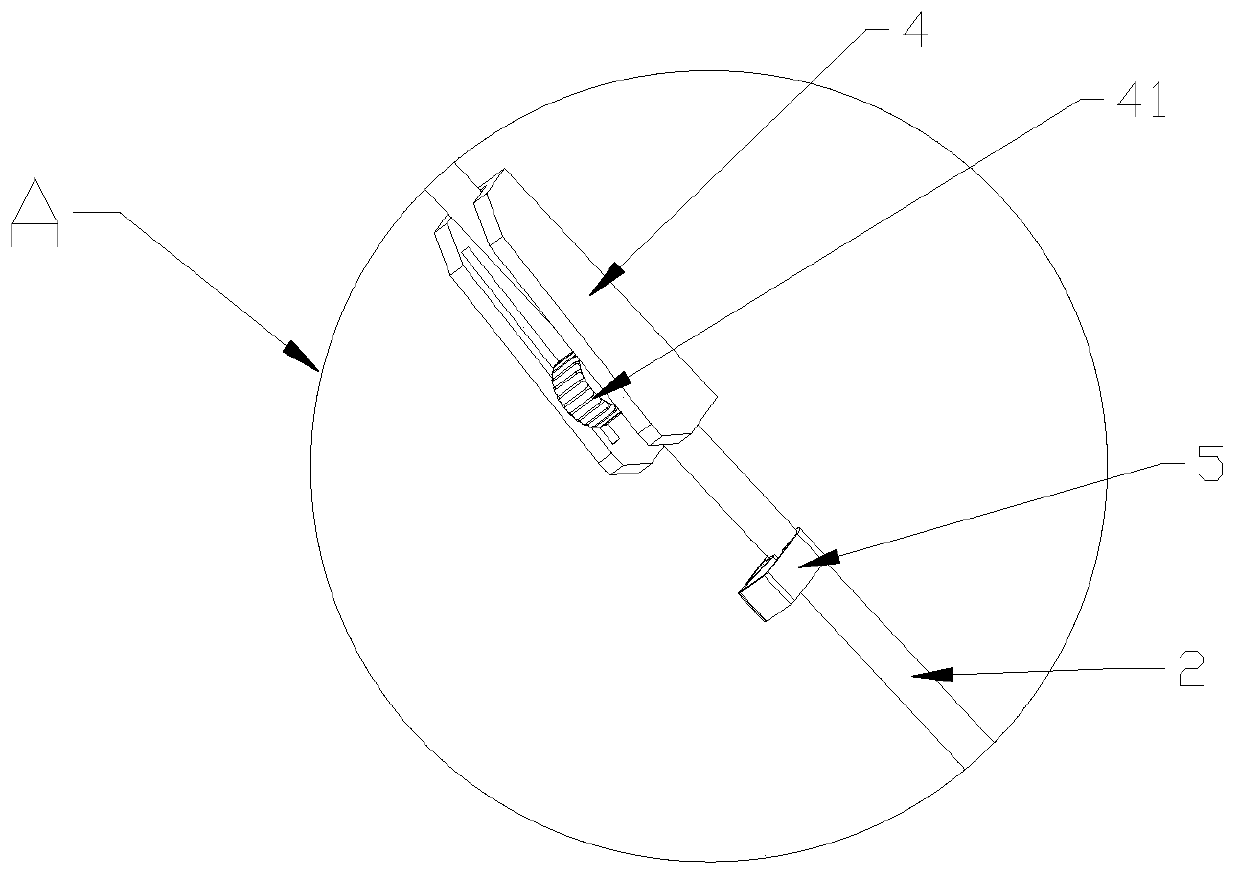
The invention discloses an improved peritoneal dialysis device, which comprises a liquid medicine bag. An infusion tube is arranged below the liquid medicine bag; a dropper is arranged on infusion tube; a pulley type switch is arranged below the dropper; the infusion tube penetrates through the pulley type switch; a pipe clamp is arranged below the pulley type switch; the infusion tube also penetrates through the pipe clamp; a main pipe and a waste liquid pipe are arranged at the top end of the infusion tube; the infusion tube is connected with the main pipe and the waste liquid pipe in a Y-shaped pipe mode; a connector is arranged at the top end of the main pipe; a pipe clamp is also arranged on the waste liquid pipe; and a thermochromic disc is arranged below the waste liquid pipe and connected with a waste liquid bag. The peritoneal dialysis device can clearly observe the peritoneal dialysis liquid injection flow velocity; tube blockage is avoided; observation, control and scheme adjustment during peritoneal dialysis operation are facilitated; the liquid inlet amount of a peritoneal dialysis liquid is conveniently observed; peritoneal dialysis related specimens are convenientlyand accurately reserved; specimen data accuracy and sterility are improved; and with the arrangement of the thermochromic disc on the waste liquid pipe, whether a waste liquid is discharged or not canbe judged by observing discoloration.

Description

technical field [0001] The invention belongs to the field of medical appliances, in particular to an improved peritoneal dialysis device. Background technique [0002] With the continuous development of modern society, chronic kidney disease has gradually become a common disease, which often requires peritoneal dialysis (PD, referred to as peritoneal dialysis) for treatment. Peritoneal dialysis is a dialysis method that uses the body's own peritoneum as a dialysis membrane. The dialysate infused into the peritoneal cavity exchanges solutes and water with the plasma components of the capillaries on the other side of the peritoneum to remove residual metabolites and excess water in the body, and at the same time replenish the necessary substances for the body through the dialysate. Through continuous renewal of peritoneal dialysis fluid, the purpose of renal replacement or supportive treatment can be achieved. Peritoneal dialysis has become an important renal replacement ther...

Claims


Application Information

Patent Timeline
Patent Type & Authority Applications(China)
IPC IPC(8): A61M1/28
CPCA61M1/1601A61M1/28
Inventor 徐媛
Owner 徐媛
Why Eureka
Try Eureka