Fertilizer applying equipment for agricultural machinery

A technology for agricultural machinery and equipment, applied in the field of fertilization equipment for agricultural machinery, can solve problems such as affecting the full mixing of soil and fertilizer, and achieve the effects of avoiding clogging, ensuring uniformity, and improving uniformity

Inactive Publication Date: 2020-08-04
程道顺
View PDF0 Cites 1 Cited by
  • Summary
  • Abstract
  • Description
  • Claims
  • Application Information

AI Technical Summary

Problems solved by technology

[0004] Based on the technical problem that the existing fertilization equipment cannot directly cover the soil on the fertilizer after the fertilization is completed, which affects the thorough mixing of the soil and the fertilizer, the present invention proposes a fertilization equipment for agricultural machinery

Method used


Image

  • Fertilizer applying equipment for agricultural machinery
  • Fertilizer applying equipment for agricultural machinery
  • Fertilizer applying equipment for agricultural machinery

Examples


Embodiment 1

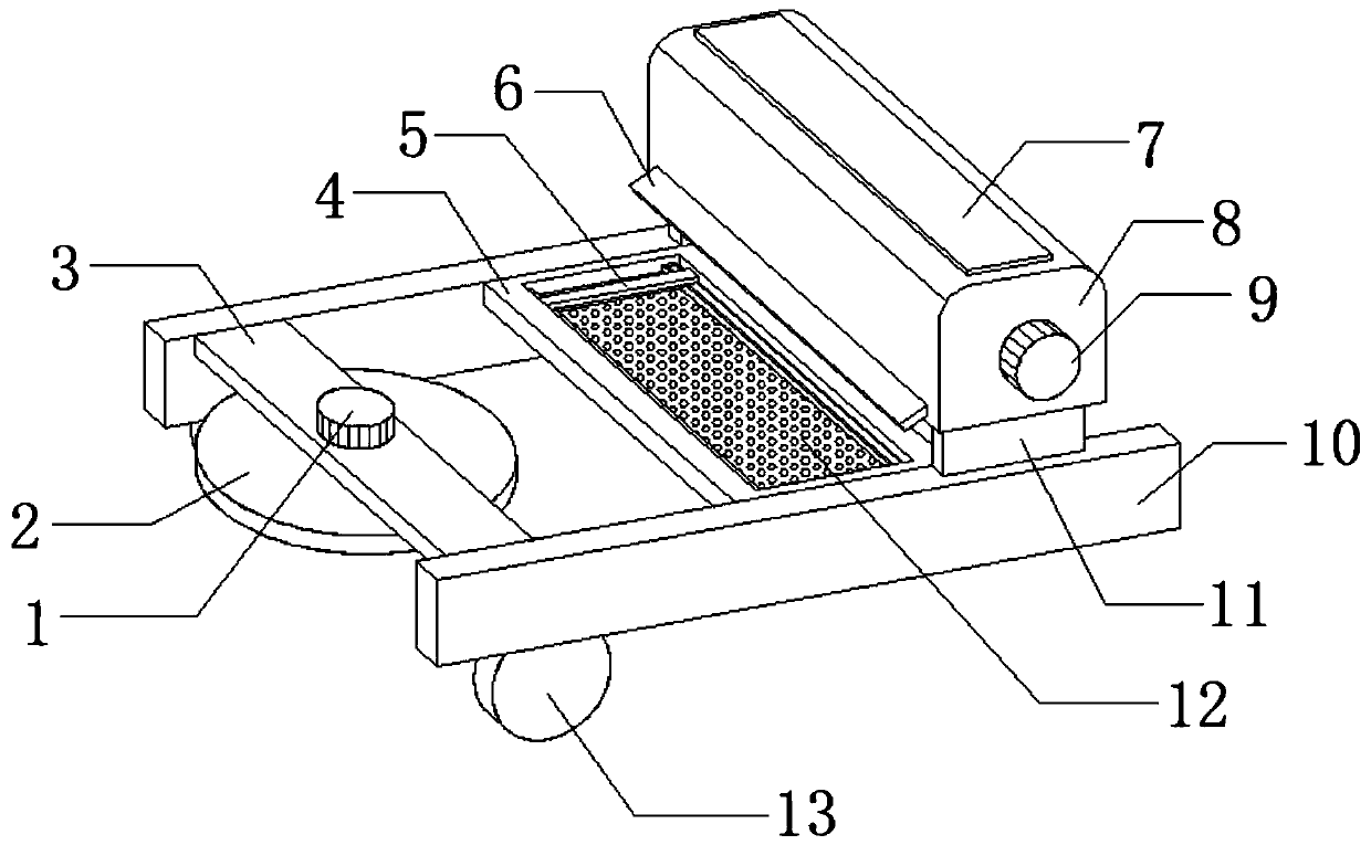
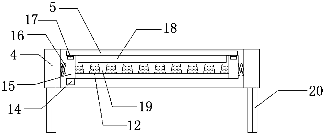
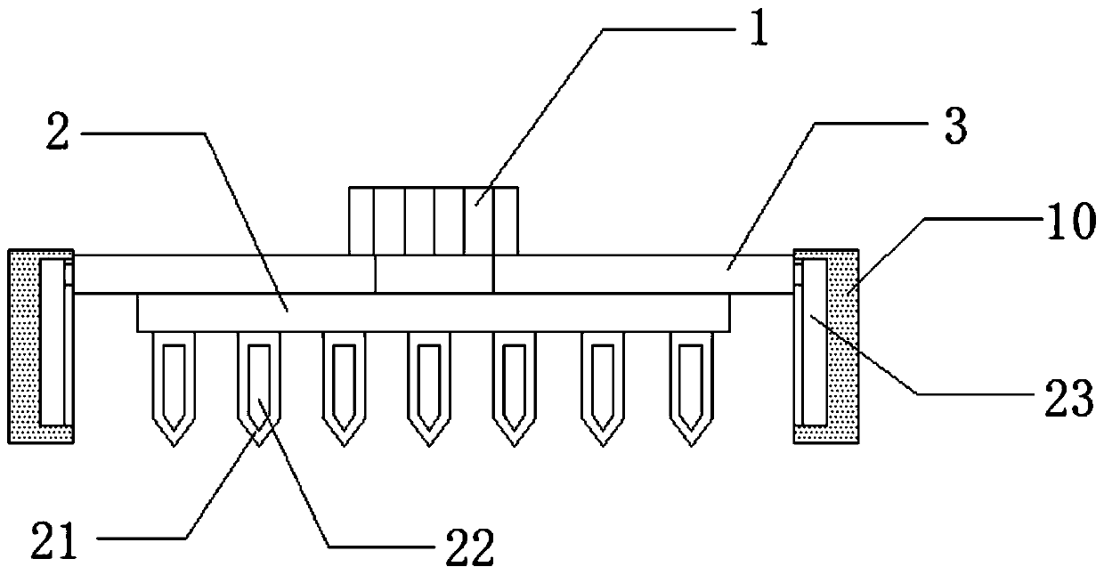
[0032] refer to Figure 1-6, a fertilizing equipment for agricultural machinery, comprising two first mounting plates 10 and two rollers 13, the two rollers 13 are respectively installed on the outer wall of the bottom side of the two first mounting plates 10 by bolts, the two first mounting plates The outer walls on one side of the top of the plate 10 are all connected with a third support plate 11 by bolts, and the outer walls of the top of the two third support plates 11 are connected with the same material storage box 8 by bolts, and the bottom of the side of the material storage box 8 The discharge pipe 6 is connected by bolts, the top outer wall of the material storage box 8 is provided with a feed inlet, and the outer wall on one side of the top of the feed inlet is connected with a feed cover 7 through a hinge, and the two first mounting plates 10 are adjacent The middle outer wall of one end is provided with a first groove, and the inner walls of the two first grooves...

Embodiment 2

[0042] refer to Figure 1-7 , a fertilizing equipment for agricultural machinery, further comprising a third rotating motor 29 mounted on the outer wall at one end of one of the first mounting plates 10 through bolts, and the output shaft of the third rotating motor is connected with a rotating roller 31 through bolts, and the rotation The outer peripheral wall of the roller 31 is connected with third turning bars 30 distributed in an annular array by bolts, and the cross section of the third turning bars 30 is triangular.

[0043] Working principle: when in use, before fertilization, the third turning motor 29 can drive the turning roller 31 and the third tilling bar 30 to rotate, and then the third turning bar 30 can perform preliminary turning of the soil, which improves the efficiency of soil crushing. Effect, which in turn facilitates the convenience of soil and fertilizer mixing.


PUM


Abstract

The invention belongs to the technical field of agricultural machinery, in particular to fertilizer applying equipment for agricultural machinery. For the problem that existing fertilizer applying equipment cannot directly cover a fertilizer with soil after fertilizer applying is completed to affect thorough mixing of the soil and the fertilizer, the scheme is proposed as follows: the fertilizer applying equipment comprises two first mounting plates and two idler wheels, wherein the two idler wheels are arranged on outer walls at one sides of the bottoms of the two first mounting plates through bolts separately; and third support plates are fixedly arranged on the outer walls at one sides of the tops of the two first mounting plates separately. According to the fertilizer applying equipment for the agricultural machinery provided by the invention, first soil turning rods are arranged at two sides of the bottom of an annular support plate, the two first soil turning rods are arranged atan interval, the first soil turning rod at one side of a storage tank body pushes the soil aside and then applies the fertilizer, and then the first soil turning rod at the other side covers the turned soil to cover the fertilizer with the soil, so that the thorough mixing of the fertilizer and the soil is ensured and the fertilizer applying effect is improved.

Description

technical field [0001] The invention relates to the technical field of agricultural machinery, in particular to fertilizing equipment for agricultural machinery. Background technique [0002] Agricultural machinery refers to various machinery used in crop planting and animal husbandry production, as well as in the primary processing and handling of agricultural and animal products. Agricultural machinery includes agricultural power machinery, farmland construction machinery, soil tillage machinery, planting and fertilization machinery, plant protection machinery, farmland drainage and irrigation machinery, crop harvesting machinery, agricultural product processing machinery, animal husbandry machinery and agricultural transportation machinery, etc. [0003] At present, in the process of fertilizing farmland, a kind of fertilization equipment is needed, but in the process of using the existing fertilization equipment, the soil is directly covered on the fertilizer after the f...

Claims


Application Information

Patent Timeline
Patent Type & Authority Applications(China)
IPC IPC(8): A01B49/06A01C15/00A01C15/12
CPCA01B49/065A01C15/00A01C15/005A01C15/12
Inventor 刘金涌
Owner 程道顺
Why Eureka
Try Eureka