Field shear test method
A shear test, on-site technology, applied in the direction of using a stable shear force to test the strength of materials, using a stable tension/pressure test to test the strength of materials, instruments, etc., can solve the complicated operation steps and the traditional methods are difficult to operate. and other problems, to achieve the effect of accurate data, uniform force, and reduced test cost
- Summary
- Abstract
- Description
- Claims
- Application Information
AI Technical Summary
Problems solved by technology
Method used
Image
Examples
Embodiment 1
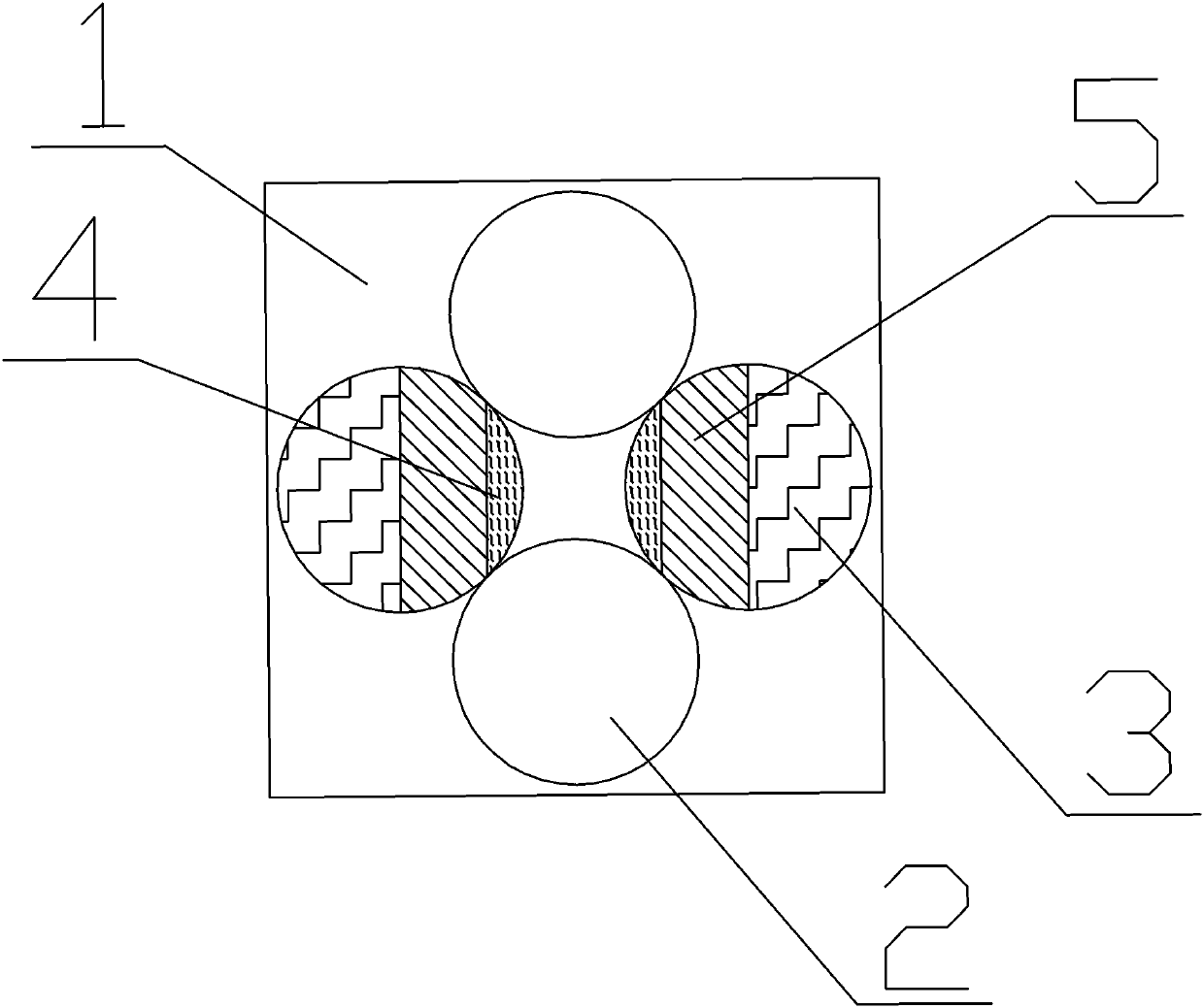
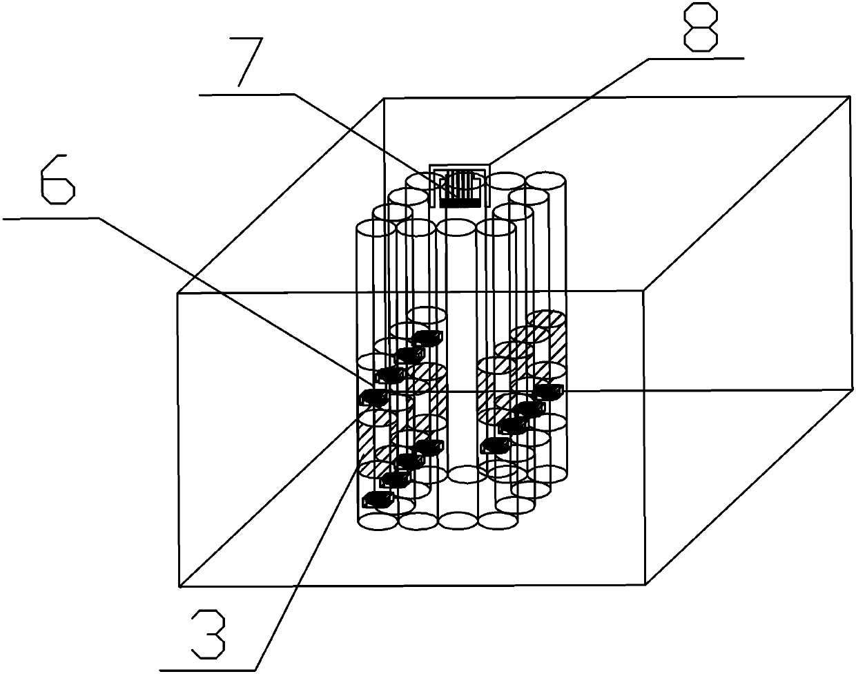
[0053] See Figure 1-10 , The field shear test method, which includes the following steps:
[0054] Step 1: Perform drilling operations on the rock and soil mass 1 on site to form holes 2 and make multiple holes 2 enclose the designated shear area of the rock and soil mass 1;
[0055] Step 2: Select the hole 2 on one side, and install the compressive stress sheet 4 for monitoring the stress inside it to realize the in-situ test of the shear stress of the rock and soil body 1;
[0056] Step 3: Install gasket 5 close to the position of compressive stress sheet 4;
[0057] Step 4: Fill multiple sets of relative holes 2 with an expansion agent 3, and the expansion agent 3 generates an expansion force on the hole 2 where the compressive stress sheet 4 is installed, so that the rock and soil body 1 has a dislocation effect, and the stress is monitored in real time;
[0058] Step 5: When the designated shear area of the rock-soil body 1 is damaged, the test ends, and the water in the caps...
Embodiment 2
[0061] Further, the working conditions that can be simulated by the test method include: simulating rainfall working conditions by pouring water into the hole 2;
[0062] Furthermore, by loading the top of the rock-soil mass 1, the shear stress conditions under different normal stresses are simulated;
[0063] Furthermore, by filling the holes 2 with different depths layer by layer with the expansion agent 3, the shear stress of each layer is monitored, and the multi-layer and multi-directional shear stress conditions are simulated.
[0064] Further, the filling method of the expansion agent 3 in the step 4 is that the bottom of a hole 2 of a certain group and its relatively high position relative to the hole 2 are filled in multiple groups of relative holes;
[0065] Further, in the step 4, the expansive agent 3 generates an expansive force, which causes the designated rock and soil shear area to produce dislocation and deformation, thereby causing shear failure. At the moment of fail...
Embodiment 3
[0078] Single-layer shear construction steps:
[0079] Step1: Drill holes 2 in the rock and soil mass 1 according to the pre-planning;
[0080] Step2, select the hole 2 on one side and paste the compressive stress sheet 4 on the side close to the rock and soil 1, and install the gasket 5 close to the compressive stress sheet 4;
[0081] Step3, put the expansion agent reaction box containing the expansion agent in the relatively high position of the hole 2 selected by Step2 and its opposite hole 2;
[0082] Step4, wait for the expansion agent 3 to generate expansion force, and monitor the stress in real time;
[0083] Step5: When the designated rock-soil body is damaged in the shearing area, the test ends, and the water in the capsule of the steel gasket is extracted to recover the gasket 5.
[0084] Step6, backup the measured data of the shear test, and analyze the test data later.
PUM
 Abstract
Description
Claims
Application Information
 - Generate Ideas
- Intellectual Property
- Life Sciences
- Materials
- Tech Scout
- Unparalleled Data Quality
- Higher Quality Content
- 60% Fewer Hallucinations
Browse by: Latest US Patents, China's latest patents, Technical Efficacy Thesaurus, Application Domain, Technology Topic, Popular Technical Reports.
© 2025 PatSnap. All rights reserved.Legal|Privacy policy|Modern Slavery Act Transparency Statement|Sitemap|About US| Contact US: help@patsnap.com


