
Ash removing device for deposited ash for boiler bellows

A technology of bellows and ash accumulation, applied in the boiler field, can solve the problems of large size of ash collecting bucket, inability to install, easy jamming, etc.

Pending Publication Date: 2020-07-31
YANTAI LONGYUAN POWER TECH
View PDF0 Cites 1 Cited by
  • Summary
  • Abstract
  • Description
  • Claims
  • Application Information

AI Technical Summary

Problems solved by technology

The former ash removal method has high energy consumption and low efficiency, and there is a large ash removal dead zone; because the degree of ash accumulation and whether ash accumulation cannot be detected, the ash removal operation is blind, resulting in a further increase in energy consumption
The latter also cannot judge the degree of ash accumulation, and the ash removal operation is blind; the working environment of the solenoid valve and the globe valve in the high temperature and high dust environment is harsh, easy to jam, and low in reliability
In addition, for the latter, due to the large size of the ash collecting hopper, it is generally only installed in the bottom burner air box, and cannot be installed in the middle and upper layer air boxes, which will affect the ash removal effect in various places in the air box
Although it can be installed in the bellows on the bottom, middle and upper layers respectively, the ventilation area of ​​the bellows is reduced due to the small-sized ash collecting hopper with an air locker, which increases the flow resistance of the secondary air, which is not conducive to the flow of the secondary air, thus aggravating Solved the problem of fly ash deposition in the bellows

Method used


Image

  • Ash removing device for deposited ash for boiler bellows
  • Ash removing device for deposited ash for boiler bellows
  • Ash removing device for deposited ash for boiler bellows

Examples


Embodiment Construction

[0038] The following will clearly and completely describe the technical solutions in the embodiments of the present invention with reference to the accompanying drawings in the embodiments of the present invention. Obviously, the described embodiments are only some, not all, embodiments of the present invention. Based on the embodiments of the present invention, all other embodiments obtained by persons of ordinary skill in the art without making creative efforts belong to the protection scope of the present invention.

[0039] In order to enable those skilled in the art to better understand the solution of the present invention, the present invention will be further described in detail below in conjunction with the accompanying drawings and specific embodiments.

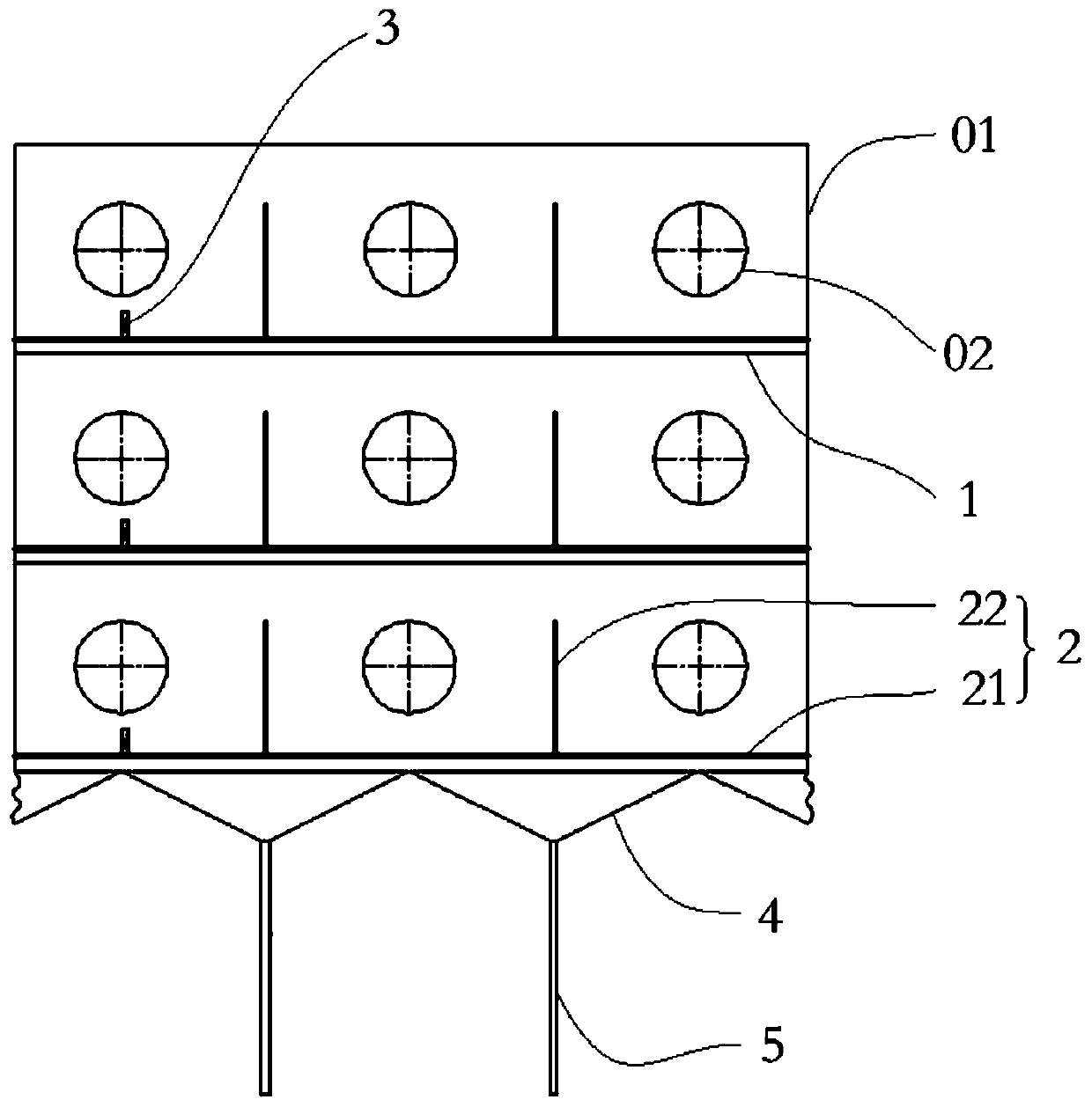
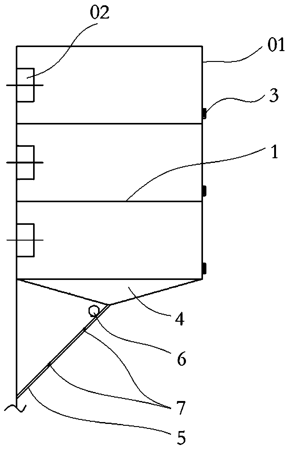
[0040] Please refer to Figure 1 to Figure 4 , figure 1 It is a schematic diagram of the assembly of the boiler air box ash removal device, air box, and burner provided by the embodiment of the present invention; ...


PUM


Abstract

The invention discloses an ash removing device for deposited ash for boiler bellows. The ash removing device comprises ash removing plates, ash removing holes, detection tracks, detectors, and an ashcollecting device, wherein the ash removing plates are arranged below a burner in the same layer in the bellows; each ash removing plate is provided with an ash removing hole being adjustable to closeand open, and used for allowing falling down of ash; the detection tracks are used for being jointed to the side walls of the bellows and respectively extent along the length direction and the thickness direction of the dust removing plates; each detector for detecting the height of deposited ash on the upper surface of the corresponding ash removing plate is in sliding connection to the inner part of the corresponding detection track; the ash removing holes are in communication when the height of the deposed ash obtained by the corresponding detector is greater than preset height; and the ash collecting device for collecting ash falling down from the ash removing holes is arranged below the ash removing plate at the bottom of the bellows. According to the ash removing device for deposited ash for boiler bellows, the ash removing holes are used for realizing communication and disconnection of cavities of the bellows above the ash removing plates with the ash collecting device, the condition that during an ash removing operation, the ash removing device for deposited ash for boiler bellows has a large ash removing area, can be guaranteed, improvement of ventilation resistance of secondary air is also avoided, and the ash removing device has the characteristics of being high in reliability, low in energy consumption and high in feasibility.

Description

technical field [0001] The invention relates to the field of boilers, in particular to an ash removal device for boiler air boxes. Background technique [0002] A coal-fired boiler is a thermal device that uses the heat released by the combustion of pulverized coal to heat the working medium water to a certain parameter steam. The air required for the combustion of pulverized coal in the furnace enters the furnace through the secondary wind box. During the actual operation, the fly ash formed by the combustion of pulverized coal will be partially deposited in the regenerator covered with corrugated plates in the rotary air preheater. When the secondary air flows through the heat storage body, it will carry the fly ash attached and deposited here into the bellows. As the circulation area of ​​the secondary air in the bellows increases, the wind speed decreases, resulting in a decrease in the ability of the secondary air to carry fly ash, and part of the fly ash is deposited ...

Claims


Application Information

Patent Timeline
IPC IPC(8): F23J1/00F23J3/00
CPCF23J1/00F23J3/00
Inventor 相明辉武学谦孙鹏宵张超群崔星源庞明军张振鲁李俊毅李明花勤健
Owner YANTAI LONGYUAN POWER TECH
Learn More