
Garbage compression station

A garbage compression and box technology, which is applied in garbage transmission, garbage collection, presses, etc., can solve the problems of lowering the installation height, reducing the loading capacity of the garbage box, increasing the weight of the garbage station (box), etc., reaching the height of the device and occupying an area Small area, optimized use and structure, and flexible and changeable transport methods

Pending Publication Date: 2020-07-31
重庆捌拾玖度环保科技有限公司
View PDF1 Cites 1 Cited by
  • Summary
  • Abstract
  • Description
  • Claims
  • Application Information

AI Technical Summary

Problems solved by technology

[0002] At present, the compression device of the feeding mobile compression garbage station (box) on the market adopts the integration of the feeding compression device and the garbage bin, that is, the compression device is put into the garbage bin for compression, which takes up the space for garbage loading; in addition , when the garbage bin is full of garbage and needs to be transferred, the garbage station (box) hopper and compression device must be transferred together with the garbage bin, which also increases the weight of the garbage station (box), and increases during the transfer process of the garbage station (box). The curb quality of the garbage transfer vehicle is reduced, the loading capacity of the garbage bin is reduced, the fuel cost and the number of transportation are increased, which directly causes the garbage truck to be seriously under-loaded, and the unit transportation cost of garbage increases
[0003] In view of the above problems, in the prior art, the patent application number is CN201920585543.2, which discloses a front-mounted split-type garbage feeding compression device. This structural design, although compared with the vertical garbage compression method, reduces the installation height in the vertical direction, but still has the problem of high design height, such as figure 1 As shown, because the garbage bin 1' is in the transfer process, the hook arm truck 2' is required to move the garbage bin 1' in or out to the bottom of the aggregate compression device 3', in order to cooperate with the hook When the arm truck 2' is tilted into or out of the garbage bin 1', it is necessary to reserve enough space for the garbage bin 1' to tilt and operate. Therefore, the aggregate compression device 3' in this technical solution also A larger vertical lifting space is needed to realize the transfer operation of the hook truck 2' to the garbage bin 1', that is, when the aggregate compression device 3' in this technical solution moves to the upper limit position, the aggregate compression device 3' ' and the dustbin 1' must be kept a relatively large distance before the dustbin 1' can be moved in or out by the hook-arm truck 2'. It can be seen from this that the split-type garbage feeding compression device of this technology is lifted away from the dustbin 1', there is still the problem of high installation space requirements. In this technical solution, since the hook-arm truck 2' is required to directly transfer the garbage bin 1', it has to give up the higher demand for the space utilization rate of the garbage station.

Method used


Image

  • Garbage compression station
  • Garbage compression station
  • Garbage compression station

Examples


Embodiment 1

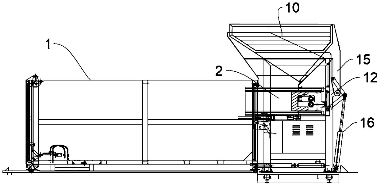
[0094] like Figure 2-Figure 12 As shown, this embodiment provides a garbage compression device station, including a feeding mechanism and a push-pull box mechanism. 3 and a drive device that drives the box body 1 to move horizontally along the box body guide rail 3 to make the feed port 4 of the box body 1 dock with the pusher bin 2 .

[0095] In this technical solution, the push-pull box mechanism drives the box body 1 to move to realize the docking between the feed port 4 of the box body 1 and the pusher silo 2, and the feeding port 4 is docked with the pusher silo 2 to facilitate feeding. After the feeding is completed, The driving device drives the box body 1 to move horizontally, so that the feed port 4 is separated from the pusher silo 2, and the box body 1 is horizontally moved out of the feeding mechanism. 1. In terms of the method of leaving enough vertical space for tilting transfer, if it is moved horizontally out of the pusher silo 2, there is no need to lift and...

Embodiment 2

[0101] This embodiment is optimized on the basis of the above-mentioned Embodiment 1.

[0102] like Figure 13-Figure 19 As shown, it also includes a lifting mechanism that drives the pusher silo 2 to move up and down.

[0103]In this technical solution, the translation and lifting functions are combined, and the push-pull box mechanism drives the box body 1 to move to realize the docking between the feeding port 4 of the box body 1 and the pusher silo 2, and the lifting mechanism adjusts the height position of the pusher silo 2. Adjustment, it is convenient to realize the docking with the feeding port 4 and the detachment from the feeding port 4. After the feeding port 4 is docked with the pusher silo 2, it is convenient to feed materials. After the feeding port 4 is separated from the pusher silo 2, it is convenient to push and pull. The box mechanism moves the box body 1 out horizontally. Since the horizontal movement is used to realize the docking and removal, it avoids t...

Embodiment 3

[0106] This embodiment is optimized on the basis of the above-mentioned Embodiment 1 or 2.

[0107] In order to facilitate the transfer of the box 1 to make room, the feeding mechanism is a mobile feeding mechanism.

[0108] Specifically, the bottom of the mobile feeding mechanism is provided with four walking wheels 7, which facilitates the overall movement of the mobile feeding mechanism. After the mobile feeding mechanism completes the feeding operation of the box 1 at the station, the lifting mechanism drives the pusher. The silo 2 is moved up to realize the separation of the pusher silo 2 and the feed port 4 of the box body 1, and then the driving device drives the box body 1 to move horizontally along the box body guide 3 to make the box body 1 detach from the feeding mechanism, and push the head material. Below the bin 2 is the box channel, that is, the driving device drives the box 1 to move out of the box channel below the pusher bin 2, and then the mobile feeding mec...


PUM


Abstract

The invention relates to the technical field of garbage compression equipment, and discloses a garbage compression device and a garbage compression station. The garbage compression device comprises afeeding mechanism and a push-pull box mechanism, wherein the feeding mechanism comprises a push head stock bin for feeding materials into a box body, the push-pull box mechanism comprises a box body guide rail extending towards the feeding mechanism and a driving device for driving the box body to horizontally move along the box body guide rail so as to enable a feeding hole of the box body to bebutted with the push head stock bin. According to the garbage compression device and the garbage compression station, the effective height needed by butt joint of the box bodies of the garbage stationis reduced, the current situation that the space height of the garbage station is limited can be better adapted, large size utilization space and feasibility are provided for transformation of an existing garbage station, a double-station or multi-station operation mode of one machine with one box or two boxes or multiple boxes is adopted, use is more reasonable and convenient, the utilization rate is higher, and the garbage treatment efficiency is higher.

Description

technical field [0001] The invention relates to the technical field of garbage compression equipment, in particular to a garbage compression device and a garbage compression station. Background technique [0002] At present, the compression device of the front feeding mobile compression garbage station (box) on the market adopts the integration of the feeding compression device and the garbage box, that is, the compression device is put into the garbage box for compression, which occupies the space for garbage loading; , When the garbage bin is full of garbage and needs to be transferred, the garbage station (box) hopper and compression device must be transferred together with the garbage can, which also increases the weight of the garbage station (box), which increases during the transfer process of the garbage station (box). The curb weight of the garbage transfer vehicle is improved, the loading capacity of the garbage bin is reduced, and the fuel cost and the number of t...

Claims


Application Information

Patent Timeline
IPC IPC(8): B65F9/00B30B9/30
CPCB30B9/30B65F9/00
Inventor 傅浪
Owner 重庆捌拾玖度环保科技有限公司
Learn More