Valve annular constriction device
A valve annulus and tensioning sheet technology, applied in the field of medical devices, can solve the problems of many complications, high risks, and difficult healing, and achieve the effect of slowing down the heart decline and improving the therapeutic effect.
- Summary
- Abstract
- Description
- Claims
- Application Information
AI Technical Summary
Problems solved by technology
Method used
Image
Examples
Embodiment 1
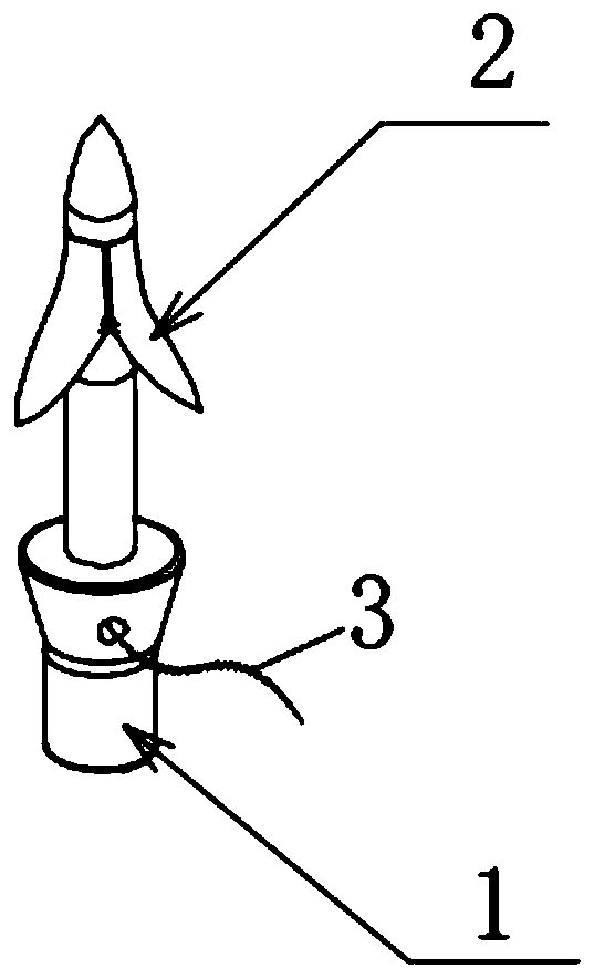
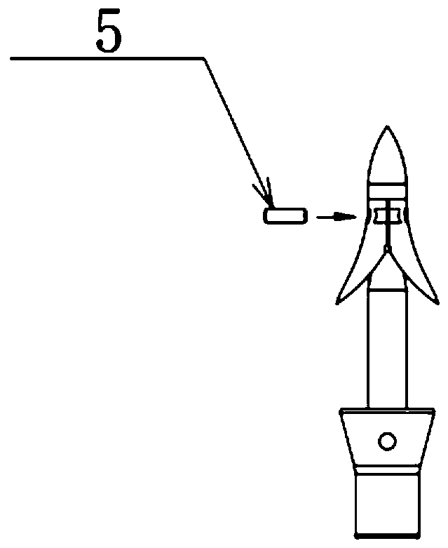
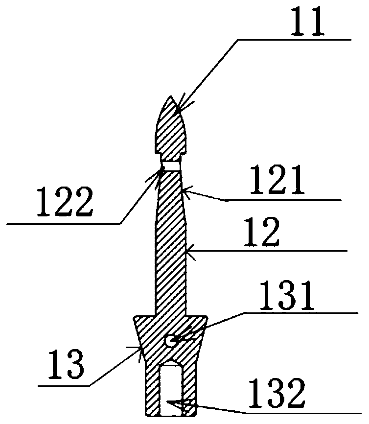
[0036] Such as Figure 1-11 As shown, this embodiment provides a valve constriction device, including an anchor 100, a tightening wire 3, and a tightening knob 4. The anchor includes an anchor needle 1, a tension piece 2, and a limit pin 5; The fixed needle 1 includes a puncture head 11, a connecting rod 12, and a base 13, wherein the puncture head 11 is similar to a tapered tip for piercing into the inner wall 8 of the ventricle; the position of the connecting rod 12 near the puncture head 11 has a limit groove 121, 2 sets of tensioning pieces are inserted on the outside of the connecting rod 12 and clamped in the limit groove 121; the middle part of the base 13 is provided with a first tightening wire hole 131 for the tightening wire 3 to pass through; the bottom of the base is provided with The first connection hole 132 is detachably connected to the push rod of the delivery device 7 , wherein the detachable connection includes threaded connection and buckle connection.
...
Embodiment 2
[0050] The valve constriction device provided in this embodiment is different from Embodiment 1 in that:
[0051] The anchor needle of this embodiment adopts a rotary structure, such as Figure 12-13 As shown, the material is memory alloy. The anchor needle is loaded in the delivery tube during delivery, and the two branches of the head end, the first head end 91a and the second head end 91b, are constrained to the axial direction by the delivery tube, and when they reach a predetermined position, the push rod is pushed to anchor the needle end The branches 91a and 91b are pierced into the target position, and the middle part of the anchor needle is rotated to form a pull ring 92, which can be used for the tightening thread 3 to pass through multiple anchor pieces for further tightening. After riveting is completed, the first head end 91a and the second head end 91b of the head branch return to the hook structure in the initial state: the first hook structure 93a and the seco...
Embodiment 3
[0054] The valve constriction device provided in this embodiment is different from Embodiment 1 in that:
[0055] The anchor in this embodiment adopts a helical structure, such as Figure 14 As shown, the head end is a needle point structure 101, the implanted part is a helical structure 102, and the connecting part is provided with a second tightening thread hole 103 for passing the tightening thread 3 so that all the anchoring devices are connected in series one by one. The end is provided with a second connection hole 104, which can be detachably connected with the push rod of the conveying device, and the connection methods include screw connection, slot connection, snap connection and the like. When the pushing rod is rotated after reaching the predetermined position, the anchoring device can be helically implanted into the human tissue, and the reverse rotation can realize the operation of long-distance detachment. After the anchoring device is implanted into human tiss...
PUM
 Abstract
Description
Claims
Application Information
 - R&D Engineer
- R&D Manager
- IP Professional
- Industry Leading Data Capabilities
- Powerful AI technology
- Patent DNA Extraction
Browse by: Latest US Patents, China's latest patents, Technical Efficacy Thesaurus, Application Domain, Technology Topic, Popular Technical Reports.
© 2024 PatSnap. All rights reserved.Legal|Privacy policy|Modern Slavery Act Transparency Statement|Sitemap|About US| Contact US: help@patsnap.com


