Spinning machine and compaction device

A technology of compression device and spinning machine, which is applied in spinning machine, continuous winding spinning machine, textile and paper making, etc., can solve the problem of inability to ensure that the hollow profile is pressed against the roller, and achieve reliable compression and uniform compression. Effect

Active Publication Date: 2020-07-28
MASCHINENFABRIK RIETER AG
View PDF10 Cites 0 Cited by
  • Summary
  • Abstract
  • Description
  • Claims
  • Application Information

AI Technical Summary

Problems solved by technology

The disadvantage of this device is that the fiber assembly may be compressed irregularly when the pressing element is accidentally pressed against the rollers of the output

Method used


Image

  • Spinning machine and compaction device
  • Spinning machine and compaction device
  • Spinning machine and compaction device

Examples


Embodiment Construction

[0035] In the following description of alternative exemplary embodiments, identical and / or at least similar features in terms of design and / or mode of operation are identified with the same reference numerals. If these features are not mentioned again in detail, their design and / or mode of operation correspond to the design and mode of function of the features already described above.

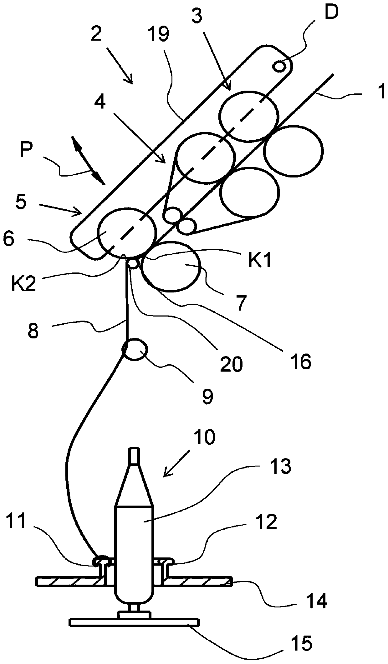
[0036] figure 1 A schematic longitudinal section of a spinning machine is shown, in particular a ring spinning machine with a compression device 20 . Several components of the spinning machine, namely the drafting device 2 and the spinning device 10 are schematically shown in the figure. The drafting device 2 is composed of three pairs of rollers: an input roller pair 3 , a belt roller pair 4 and an output roller pair 5 . The output roller pair 5 is formed by the output top roller 6 and the output cylinder 7 . The two rollers of a roller pair abut together and form a clamping point at their ...


PUM


Abstract

The invention relates to a spinning machine comprising a plurality of drawing frames (2) each for drawing a fibre composite (8) on which the top rollers of the drawing frame (2) are arranged, comprising: an output roller pair (5) which is formed by an output top roller (6) and an output cylinder (7) arranged thereunder; a longitudinal component (46) which extends substantially parallel to the output cylinder (7); and a pneumatic compaction device (20), arranged downstream of the output roller pair (5) of the drawing frame (2), for compacting the drawn fibre composite (8), said compaction device having a suction tube (17) around which a screen element (18) is wrapped and which can be subjected to suction, wherein the suction tube (17) is arranged and rotatably and/or displaceably mounted ona support (25) fastened to the machine frame (28).

Description

technical field [0001] The invention relates to a spinning machine, which has a plurality of drafting devices respectively used for drafting a fiber assembly (Faserverband), and the drafting devices respectively have: top rollers, bottom rollers and load arms, the drafting The top roller of the stretching device is arranged on the load arm; the output roller pair is formed by the output top roller and the output cylinder arranged below the output top roller; the longitudinal part, especially the punch seat, the longitudinal part is generally extending parallel to said output cylinder; and a pneumatic compression device located downstream of the pair of output rollers of said drafting device for compressing the drawn fiber assembly, said compression device having a suction pipe, said The suction tube is wound around the filter element. The invention also relates to a compression device for a drafting device with a suckable suction tube. Background technique [0002] A drafti...

Claims


Application Information

Patent Timeline
IPC IPC(8): D01H5/72D01H1/02
CPCD01H5/72D01H1/025
Inventor G·沙夫勒N·斯托普诺伯特·巴奥克
Owner MASCHINENFABRIK RIETER AG
Why Eureka
Try Eureka