Node fusion method and device and code generation method and device
A fusion method and node technology, applied in the field of data processing, can solve the problems of small computing granularity and inability to give full play to the computing performance of the hardware platform.
- Summary
- Abstract
- Description
- Claims
- Application Information
AI Technical Summary
Problems solved by technology
Method used
Image
Examples
Embodiment 1
[0026] refer to figure 1 , shows a flow chart of the steps of the node fusion method according to Embodiment 1 of the present invention.
[0027] The method comprises the steps of:
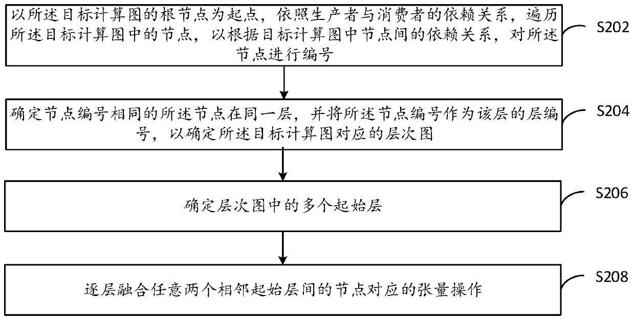
[0028] S102. Number the nodes according to the dependencies among the nodes in the target computation graph.
[0029] In this embodiment, the target computation graph may be an entire computation graph, or a subgraph of an entire computation graph, which is not limited in this embodiment.
[0030] Nodes with dependencies in the target computation graph are connected by edges, each node corresponds to a tensor operation, and each edge corresponds to a tensor.
[0031] In this embodiment, there is a dependency relationship between each node in the calculation graph, such as a data dependency relationship or a control dependency relationship, etc. During calculation, the nodes with the dependency relationship have a time sequence relationship, then in this embodiment, according to the Dependencies...
Embodiment 5
[0131] refer to Figure 5a , shows a schematic flowchart of a tensor operation and code generation method according to Embodiment 5 of the present invention. Through this embodiment, an example is given to describe the above-mentioned combination of node fusion and code generation process.
[0132] The method provided in this embodiment includes the following steps:
[0133] S502. Number the nodes in the input target computation graph.
[0134] Specifically, for the specific requirements on the input target computation graph, refer to the above step S102, which will not be repeated in this embodiment.
[0135] In this example, if Figure 5b As shown, the methods for numbering the target computation graph include:
[0136] S5021. Initialize the node in the node queue as the root node, and number the root node.
[0137] S5022. Determine whether the node queue is empty. If it is empty, end; if not empty, execute step S5023.
[0138] S5023. Pop the node at the head of the q...
Embodiment 6
[0176] refer to Figure 6 , shows a structural block diagram of a node fusion device according to Embodiment 6 of the present invention.
[0177] The device provided in this embodiment includes: a numbering module 602 and a fusion module 604 .
[0178] The numbering module 602 is used to number the nodes according to the dependencies among the nodes in the target computing graph. The nodes with dependencies in the target computing graph are connected by edges, and each node corresponds to a tensor operation. Each edge corresponds to a tensor.
[0179] The fusion module 604 is configured to determine the layer where the node is located according to the numbering result, so as to determine the layer graph corresponding to the target computation graph, and perform layer-by-layer fusion of tensor operations according to the layer graph.
[0180] In an optional implementation manner, the numbering module 602 is specifically configured to: start from the root node of the target co...
PUM
 Abstract
Description
Claims
Application Information
 - R&D
- Intellectual Property
- Life Sciences
- Materials
- Tech Scout
- Unparalleled Data Quality
- Higher Quality Content
- 60% Fewer Hallucinations
Browse by: Latest US Patents, China's latest patents, Technical Efficacy Thesaurus, Application Domain, Technology Topic, Popular Technical Reports.
© 2025 PatSnap. All rights reserved.Legal|Privacy policy|Modern Slavery Act Transparency Statement|Sitemap|About US| Contact US: help@patsnap.com


