
Centrifugal fan and electrical equipment

A centrifugal fan and electrical equipment technology, applied in the direction of mechanical equipment, machines/engines, lighting and heating equipment, etc., can solve the problem of small air volume of centrifugal fans, and achieve the effect of reducing rotation noise, reducing noise and reducing volume

Pending Publication Date: 2020-07-28
FOSHAN SHUNDE MIDEA WASHING APPLIANCES MFG CO LTD
View PDF0 Cites 3 Cited by
  • Summary
  • Abstract
  • Description
  • Claims
  • Application Information

AI Technical Summary

Problems solved by technology

[0003] The main purpose of the present invention is to propose a centrifugal fan and electrical equipment, aiming at improving the problem of small air volume of the existing centrifugal fan

Method used


Image

  • Centrifugal fan and electrical equipment
  • Centrifugal fan and electrical equipment
  • Centrifugal fan and electrical equipment

Examples


Embodiment Construction

[0037] The following will clearly and completely describe the technical solutions in the embodiments of the present invention with reference to the accompanying drawings in the embodiments of the present invention. Obviously, the described embodiments are only some of the embodiments of the present invention, not all of them. Based on the embodiments of the present invention, all other embodiments obtained by persons of ordinary skill in the art without creative efforts fall within the protection scope of the present invention.

[0038] It should be noted that if there is a directional indication (such as up, down, left, right, front, back...) in the embodiment of the present invention, the directional indication is only used to explain the relationship between the components in a certain posture. If the specific posture changes, the directional indication will also change accordingly.

[0039] In addition, if there are descriptions involving "first", "second" and so on in the...


PUM


Abstract

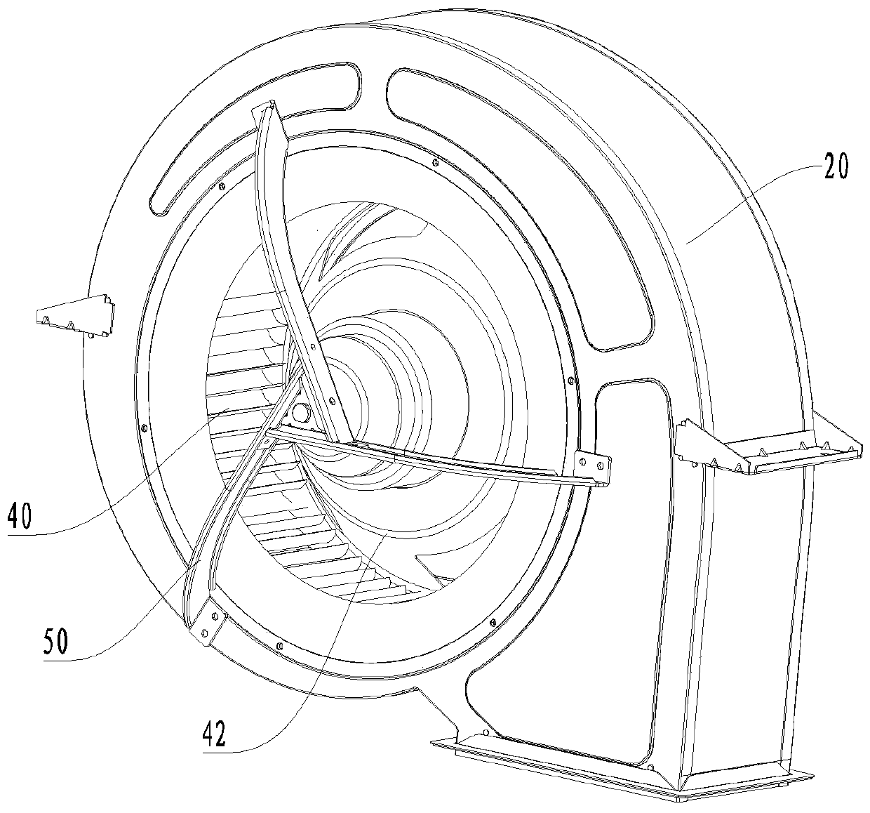
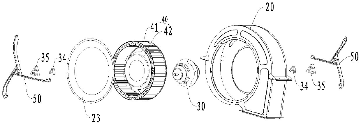
The invention discloses a centrifugal fan and electrical equipment. The centrifugal fan comprises a volute, an impeller, an outer rotor motor and supports. Air inlets are formed in the two sides of the volute correspondingly. The impeller is arranged in the volute. The impeller comprises a mounting disc and multiple blades arranged on the mounting disc. The mounting disc is of a disc structure, and the multiple blades are distributed along the periphery of the mounting disc at intervals. The outer rotor motor is used for driving the impeller to rotate, the outer rotor motor is provided with astator and a rotor matched with the stator, and the rotor is connected with the mounting disc. The supports are arranged on the two air inlets correspondingly, and the two ends of the stator are connected and fixed to the corresponding supports correspondingly. The rotor of the outer rotor motor is adopted for driving the impeller, the situation that vibration generated when the impeller rotates is transmitted to the volute is avoided, and the rotating noise of the centrifugal fan is reduced. The outer rotor motor is adopted, the air resistance of the air inlets of the centrifugal fan is reduced, and the energy utilization rate of the centrifugal fan is increased.

Description

technical field [0001] The invention relates to the field of household electrical appliances, in particular to a centrifugal fan and electrical equipment. Background technique [0002] In the existing centrifugal fan of the integrated stove, the motor fixed on the volute drives the impeller to rotate, and provides negative pressure for absorbing oil fumes. Due to the narrow space at the rear end of the air duct of the integrated stove, the volume of the motor will occupy a part of the space of the air box, which not only blocks the flow channel, the air intake of the air box is not smooth, affects the air volume, but also reduces the space of other functional areas at the front end. Contents of the invention [0003] The main purpose of the present invention is to provide a centrifugal fan and electrical equipment, aiming at improving the problem of small air volume of the existing centrifugal fan. [0004] In order to achieve the above object, a centrifugal fan proposed ...

Claims


Application Information

Patent Timeline
Patent Type & Authority Applications(China)
IPC IPC(8): F04D17/16F04D25/06F04D29/42F04D29/28F04D29/30F04D29/62F04D29/66F24C15/20
CPCF04D17/16F04D29/4233F04D29/282F04D29/30F04D29/626F04D29/663F04D29/668F24C15/20F04D25/0606
Inventor 贾志强宋祖龙何新奎王佳新刘凡继蒋济武李逢钦
Owner FOSHAN SHUNDE MIDEA WASHING APPLIANCES MFG CO LTD
Learn More