High frequency hydraulic power vibration tool

A hydraulic and high-frequency technology, which is applied to drilling equipment, earthwork drilling, and driving devices for drilling in boreholes, etc., can solve the problems of percussion tool parts that are prone to fatigue damage, unsatisfactory overall effect, and low service life. Remarkable speed-up effect

Pending Publication Date: 2020-07-28
中石化石油工程技术服务有限公司 +2
View PDF0 Cites 0 Cited by
  • Summary
  • Abstract
  • Description
  • Claims
  • Application Information

AI Technical Summary

Problems solved by technology

Research and analysis of domestic and foreign data shows that the overall effect of the existing impact tools on site is not ideal, the internal parts of the impact tools are prone to fatigue damage, and the service life is low, and the existing impact tools are longer in size, which extends the blind area of ​​the downhole measurement and control instrument. Therefore, it cannot fully meet the drilling technology requirements of complex structural wells such as directional wells, horizontal wells, and extended-reach wells.

Method used


Image

  • High frequency hydraulic power vibration tool
  • High frequency hydraulic power vibration tool

Examples


Embodiment 1

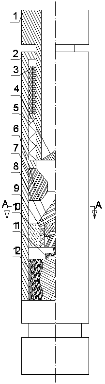
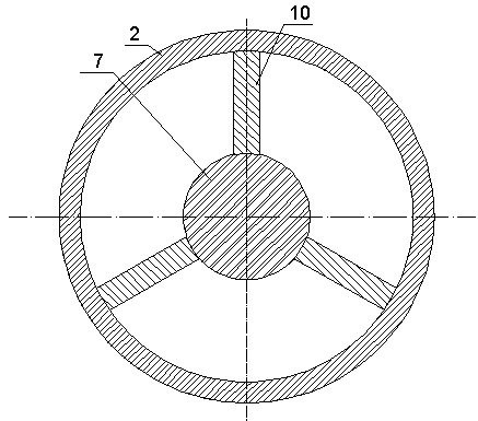
[0018] Refer to attached figure 1 and 2 , a high-frequency hydraulic vibration tool, including a central shaft 1, an outer shell 2, a spring 5, a screw motor assembly 12, a valve seat 6, a cone valve 7, an upper cam 8, a lower cam 9, ribs 10 and a connecting rod mechanism 11; wherein: a spline pair 3 is set between the central shaft 1 and the outer shell 2 to form an axial spline sliding fit; the spring 5 is installed between the central shaft 1 and the outer shell 2; the valve seat 6 is fixed on the outer shell 2 On the inner wall, and located at the lower part of the central axis 1, a rib 10 is installed between the cone valve 7 and the outer shell 2, the rib 10 and the outer shell 2 are fixedly installed, and the cone valve 7 can move axially along the rib 10; The upper cam 8 is fixedly installed inside the poppet valve 7, the lower cam 9 is installed below the upper cam 8 and is axially limited, the lower cam 9 and the upper cam 8 form a cam transmission cooperation; the ...

Embodiment 2

[0020] Such as figure 1 and 2 As shown, the high-frequency hydraulic vibration tool is mainly composed of a central shaft 1, an outer shell 2, a spline pair 3, a one-way valve 4, a spring 5, a valve seat 6, a cone valve 7, an upper cam 8, a lower cam 9, ribs Plate 10, link mechanism 11, screw motor assembly 12. The spline pair 3 is installed between the central shaft 1 and the outer casing 2, and forms a spline fit. A check valve 4 is installed on the bottom of the central shaft 1, a spring 5 is installed between the central shaft 1 and the outer casing 2, and a valve seat 6 is installed on the inner wall of the outer casing 2 and is located at the bottom of the central shaft 1. A rib 10 is installed between the poppet valve 7 and the outer casing 2 , the rib 10 and the outer casing 2 are fixedly installed, and the poppet valve 7 can move axially along the rib 10 . The upper cam 8 is fixedly installed inside the cone valve 7, the lower cam 9 is installed inside the cone val...


PUM


Abstract

The invention relates to a high frequency hydraulic power vibration tool. The high frequency hydraulic power vibration tool comprises a center shaft, an outer housing, a spring, a screw motor assembly, a valve seat, a conical valve, an upper cam, a lower cam, a rib plate and a connecting rod mechanism, wherein a mating spline is arranged between the center shaft and the outer housing to form an axial spline for sliding cooperation; the spring is mounted between the center shaft and the outer housing; the valve seat is fixed to the inner wall of the outer housing, and is located at the lower part of the center shaft; the rib plate is mounted between the conical valve and the outer housing, and is fixedly mounted on the outer housing; the conical valve can axially move along the rib plate; the upper cam is fixedly mounted in the conical valve; the lower cam is mounted below the upper cam and is limited axially; the lower cam and the upper cam form a cam transmission cooperation; and thelower cam is in transmission with a rotor of the screw motor assembly through the connecting rod mechanism. The high frequency hydraulic power vibration tool disclosed by the invention can completelymeet domestic drilling technology requirements of wells having complex constructions including straight wells, directional wells, lateral wells and the like, and is a novel tool simple in structure, convenient to operate, low in cost and safe and reliable.

Description

technical field [0001] The invention relates to a high-frequency hydraulic vibration tool in the tool fields of oil and gas drilling, coal bed gas drilling, geological exploration, mine drilling and the like. Background technique [0002] In the fields of oil and gas drilling, geological exploration, mine drilling, etc., as the depth of the well increases, the rock becomes harder and harder, which seriously restricts the rock-breaking efficiency of the drill bit. Drilling practice has proved that during the process of the drill bit rotating to break rock, applying a certain frequency of impact force on the drill bit can effectively improve the rock breaking efficiency of the drill bit. The principle of existing impact tools at home and abroad is mainly rigid impact, which belongs to low-frequency and high-amplitude impact, that is, the impact energy is large, but the frequency is low. The extension of the drilling efficiency decreases rapidly. The main reason is that the im...

Claims


Application Information

Patent Timeline
Patent Type & Authority Applications(China)
IPC IPC(8): E21B4/14
CPCE21B4/14
Inventor 李文飞周延军肖新磊王晓徐波张涛
Owner 中石化石油工程技术服务有限公司
Why Eureka
Try Eureka