A coastal slope anti-wave guardrail device

A technology of guardrail device and side slope, which is applied in the direction of coastline protection, bank walls, embankments, etc., can solve the problems of easily damaged grid guardrails, poor flexibility, and large amount of construction work of wave-blocking cement columns.

Active Publication Date: 2021-08-20
聊城鸿嘉网络技术有限公司
View PDF0 Cites 0 Cited by
  • Summary
  • Abstract
  • Description
  • Claims
  • Application Information

AI Technical Summary

Problems solved by technology

[0004] The purpose of the present invention is to solve the shortcomings in the prior art that there is a large amount of construction work for the wave-stopping cement column, and it cannot be changed with the construction plan or climate, the flexibility is poor, the grid guardrail is easily damaged, and the shortcomings that require frequent maintenance are proposed. A coast slope anti-wave guardrail device

Method used


Image

  • A coastal slope anti-wave guardrail device
  • A coastal slope anti-wave guardrail device
  • A coastal slope anti-wave guardrail device

Examples


Embodiment 1

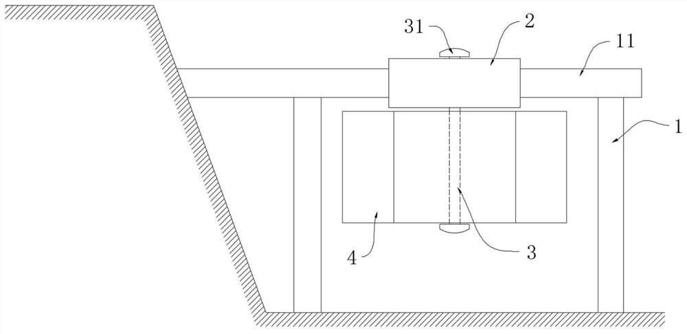
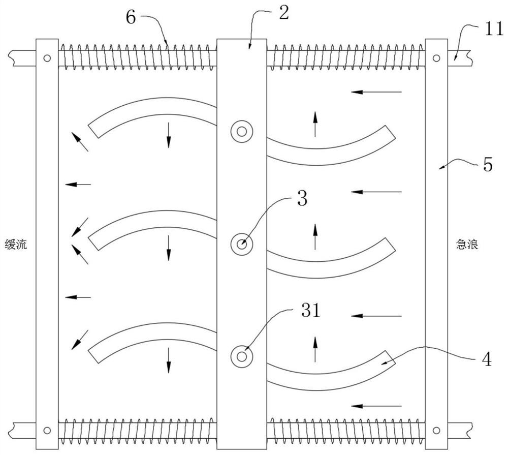
[0028] refer to Figure 1-2 , a coastal slope anti-wave guardrail device, including a fixed frame 1, the fixed frame 1 includes two horizontal bars 11 arranged in parallel, the sliding sleeves on the two horizontal bars 11 are provided with a sliding plate 2, and the horizontal bar 11 is located on the sliding plate 2 Two limit rods 5 are symmetrically fixedly installed on both sides of each horizontal rod 11, and two springs 6 are symmetrically sleeved on each horizontal rod 11, and each spring 6 is connected to the sliding plate 2 and the limit rod 5, and on the sliding plate 2 A plurality of rotating shafts 3 are inserted for rotation, and each rotating shaft 3 is provided with a double-arc spoiler 4 at the lower end of the sliding plate 2 , and locking caps 31 are installed at both ends of the rotating shaft 3 .

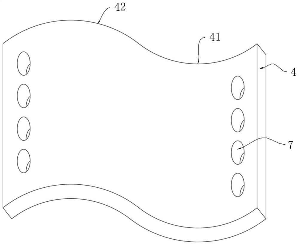
[0029] Both ends of the double-arc spoiler 4 include a concave arc surface 41 and a convex arc surface 42;

[0030] When the wave gathers force and passes throu...

Embodiment 2

[0035] refer to Figure 3-4 , a coastal slope anti-wave guardrail device, which is basically the same as Embodiment 1, the difference is that:

[0036] Both ends of the double-arc spoiler 4 are symmetrically provided with a plurality of spoiler holes 7, and a spoiler 8 is rotatably installed in each spoiler hole 7;

[0037] The impact of seawater makes the double-arc spoiler 4 continuously rotate and swing to disperse the waves. , part of the water flows through the spoiler hole 7, reducing the impact of seawater on the double-arc spoiler 4, and avoiding damage under high-intensity impact, and the spoiler hole 7 can The seawater flowing through is stirred irregularly, making the wake of the double-arc spoiler 4 more chaotic and colliding with each other to lose the accumulated potential energy, and the spoiler 8 can further increase the flow of seawater through the spoiler hole 7. Uncertainty increases the ability of the device to disperse the potential energy of ocean waves...


PUM


Abstract

The invention discloses a coast slope anti-wave guardrail device, comprising a fixed frame, the fixed frame includes two horizontal bars arranged in parallel, sliding sleeves on the two horizontal bars are provided with sliding plates, and the horizontal bars are located at Two limit rods are symmetrically fixed on both sides of the sliding plate, and two springs are symmetrically sleeved on each of the horizontal rods, and each spring is connected to the sliding plate and the limit rod, and the sliding plate rotates A plurality of rotating shafts are inserted, each of which is located at the lower end of the sliding plate and is provided with a double-arc spoiler, and both ends of the rotating shaft are equipped with lock caps. The invention swings and disperses the impact of seawater through the double-arc spoiler impacted by seawater, and the dispersed seawater collides with each other to offset the impact force, increasing the anti-wave capability of the device, and installing the double-arc spoiler on the shaft and lock cap The sliding plate can be quickly disassembled and installed to increase the flexibility of the device, and the ability of the device to impact and disrupt seawater is further increased through spoiler holes and spoilers.

Description

technical field [0001] The invention relates to the field of coastal wave prevention, in particular to a coastal slope anti-wave guardrail device. Background technique [0002] The ocean is the largest source of water on the earth, and the land cycle of the ocean is also the largest water cycle. The ocean provides humans and animals with the largest source of fresh water, but there will also be harsh weather such as tsunamis and typhoons at sea. The harsh climate causes seawater to gather and form a scale. Larger waves, excessive waves will cause damage to coastal areas, so it needs to be protected. [0003] Existing anti-wave devices usually build unevenly distributed wave-resistant concrete columns on the coast to reduce the impact of waves by dispersing the potential energy of waves. After completion, it will be in a fixed state and cannot be changed with regional construction or regional climate. Its flexibility is low, and some anti-wave fences prevent waves from direc...

Claims


Application Information

Patent Timeline
Patent Type & Authority Patents(China)
IPC IPC(8): E02B3/06
CPCE02B3/06Y02A10/11
Inventor 吴艳芳耿辉徐超
Owner 聊城鸿嘉网络技术有限公司
Why Eureka
Try Eureka