
Feeding equipment for universal angle steel electric arc refining

An angle steel and arc technology, which is applied in the field of feeding equipment for universal angle steel arc refining, can solve the problems of affecting the working environment of the factory, dust flying, heat loss of electric arc furnace and increased energy consumption, etc.

Inactive Publication Date: 2020-07-28
杭州酬催科技有限公司
View PDF0 Cites 0 Cited by
  • Summary
  • Abstract
  • Description
  • Claims
  • Application Information

AI Technical Summary

Problems solved by technology

[0003] In traditional steelmaking electric arc furnaces, in order to prevent insufficient reaction of steelmaking raw materials due to excessive materials, the materials need to be loaded from the furnace top several times, and rely on the electric arc generated between symmetrical electrodes and steelmaking raw materials. Melting raw materials for steelmaking; so the traditional electric arc furnace can only send power to the furnace intermittently according to the feeding time, and it is necessary to cut off the power at each interval and unscrew the furnace cover to charge, which not only reduces the productivity of the electric arc furnace , and increase the heat loss and energy consumption of the electric arc furnace; in addition, when the furnace cover is opened, a large amount of dust will fly out, seriously affecting the working environment of the factory, so a kind of feeding equipment for universal angle steel electric arc refining came into being

Method used


Image

  • Feeding equipment for universal angle steel electric arc refining
  • Feeding equipment for universal angle steel electric arc refining
  • Feeding equipment for universal angle steel electric arc refining

Examples


Embodiment Construction

[0022] The following will clearly and completely describe the technical solutions in the embodiments of the present invention with reference to the accompanying drawings in the embodiments of the present invention. Obviously, the described embodiments are only some, not all, embodiments of the present invention. Based on the embodiments of the present invention, all other embodiments obtained by persons of ordinary skill in the art without making creative efforts belong to the protection scope of the present invention.

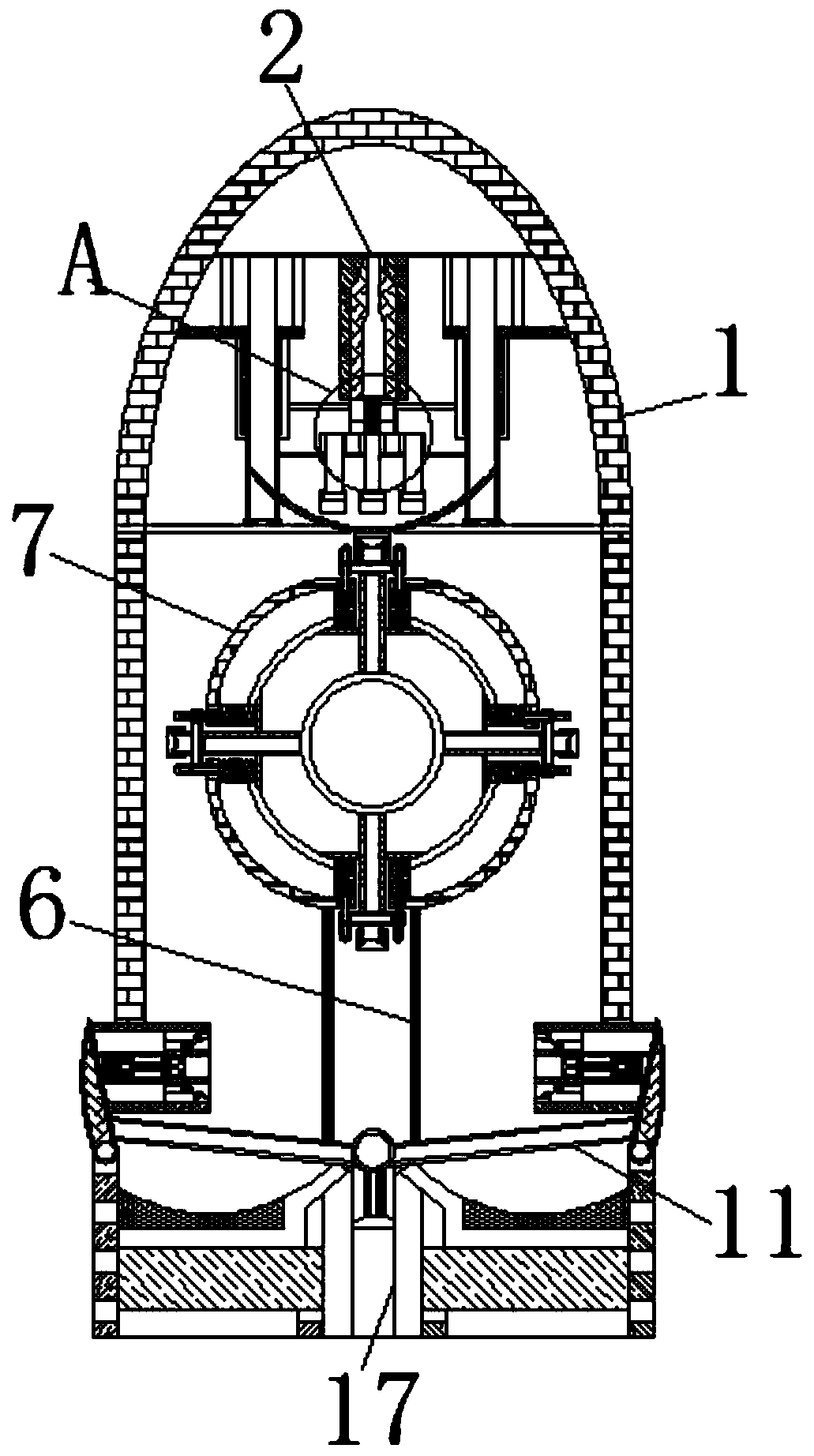
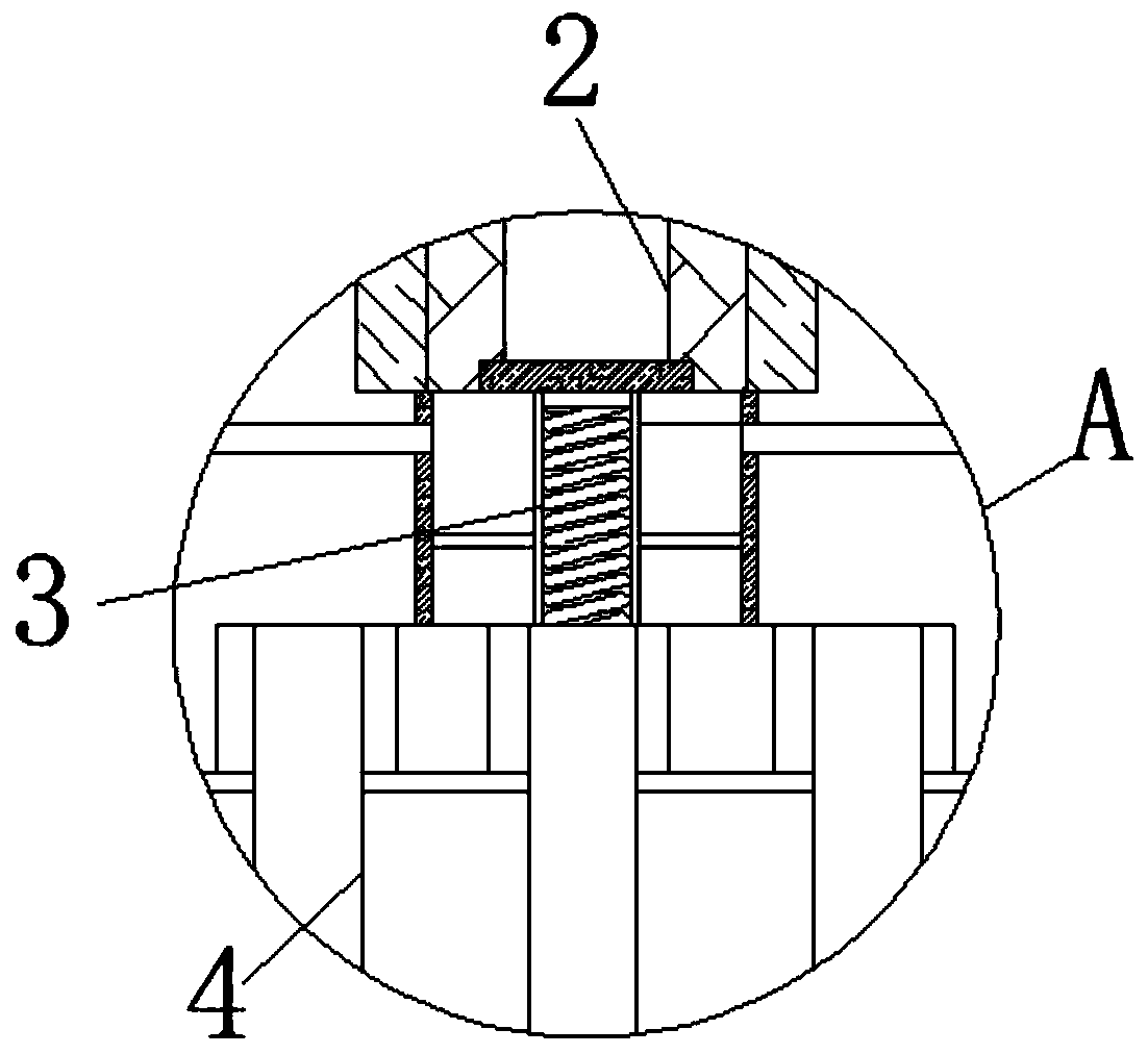
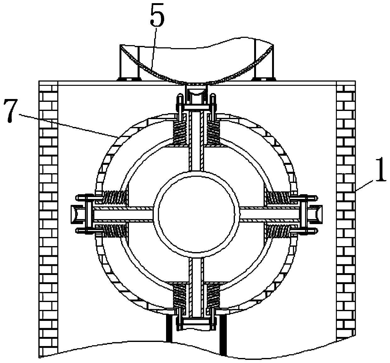
[0023] see Figure 1-6 , a feeding equipment for universal angle steel arc refining, including a shell 1, the shell 1 and the internal parts of the shell 1 are all high temperature and high pressure resistant materials, the high temperature and high pressure resistant material is mica high temperature and high pressure resistance and heat insulation, some of our country When muscovite is heated at 100-600 °C, the elasticity and surface properties remain unchan...


PUM


Abstract

The invention relates to the technical field of universal angle steel refining, and discloses feeding equipment for universal angle steel electric arc refining. The feeding equipment comprises a shell, a feeding port is fixedly connected into the shell, a compression spring is movably connected into the feeding port, a material distribution pipe is movably connected to the lower end of the compression spring, and a material seepage plate is movably connected to the bottom of the material distribution pipe; a sliding rail is arranged in the shell and located at the bottom of the material seepage plate, a rotating plate is slidably connected to the surface of the sliding rail, a spring frame is movably connected to the surface of the rotating plate, and an extendable rod is movably connectedto the surface of the spring frame; and a bearing plate is movably connected to the surface of the extendable rod, a push rod is movably connected to the lower end of the sliding rail, and one end ofthe push rod away from the slide rail is movably connected with an arc box. The push rod moves upwards, so that materials on the surface of the push rod flow out of a feeding pipe, the materials fallon the surface of the push rod in batches due to the rotating effect of the rotating plate, and therefore the effect that the materials are sequentially thrown as needed according to the electric arcsteelmaking process without uncovering is achieved.

Description

technical field [0001] The invention relates to the technical field of universal angle steel refining, in particular to a feeding device for universal angle steel arc refining. Background technique [0002] Universal angle steel is the same type of steel, but the name is different; it is a type of steel specially used for making shelves. It has various shapes and many long holes for people to string screws. It is mainly used for individual shelves in shopping malls and factories; in order to respond In response to the call of the state for energy conservation and environmental protection, the universal angle steel is now made of electric furnace steel using scrap steel as raw material. [0003] In traditional steelmaking electric arc furnaces, in order to prevent insufficient reaction of steelmaking raw materials due to excessive materials, the materials need to be loaded from the furnace top several times, and rely on the electric arc generated between symmetrical electrode...

Claims


Application Information

Patent Timeline
IPC IPC(8): C21C5/52
CPCC21C5/527Y02P10/20
Inventor 葛兆胜
Owner 杭州酬催科技有限公司
Learn More