Intermittent rotation and middle punching device for glass vase

A vase and glass technology, applied in the field of intermittent rotation and middle hole opening device, can solve the problem of low hole opening efficiency of glass vases, and achieve the effect of increasing uniformity

Pending Publication Date: 2020-07-28
秦胜
View PDF7 Cites 0 Cited by
  • Summary
  • Abstract
  • Description
  • Claims
  • Application Information

AI Technical Summary

Problems solved by technology

[0004] In order to solve the above-mentioned technical problems, the present invention provides an intermittent rotation and middle hole opening device for glass vases to solve the problem of low efficiency of opening holes in the middle of glass vases

Method used


Image

  • Intermittent rotation and middle punching device for glass vase
  • Intermittent rotation and middle punching device for glass vase
  • Intermittent rotation and middle punching device for glass vase

Examples


Embodiment 1

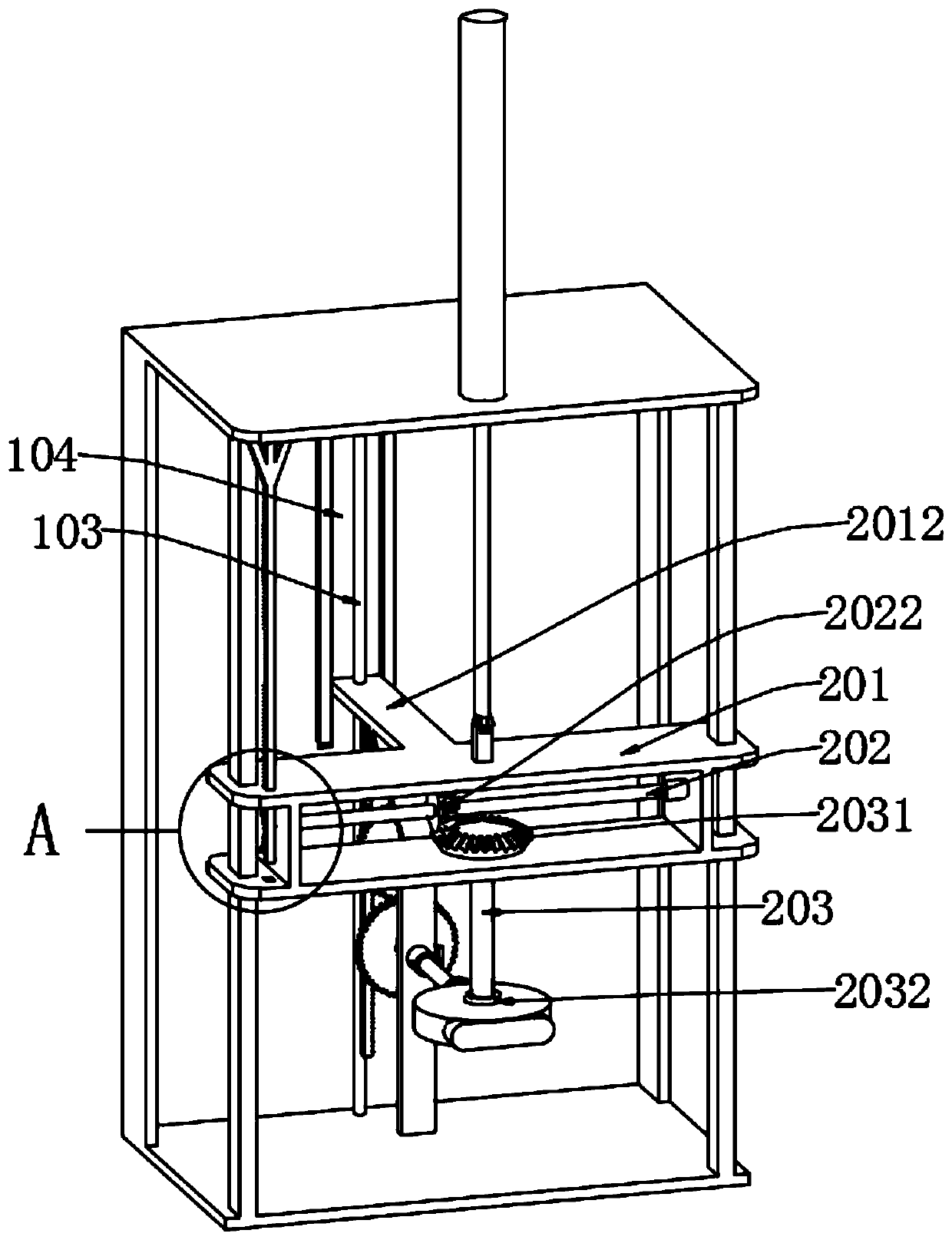
[0031] as attached Figure 1-3 to attach Figure 7 Shown:

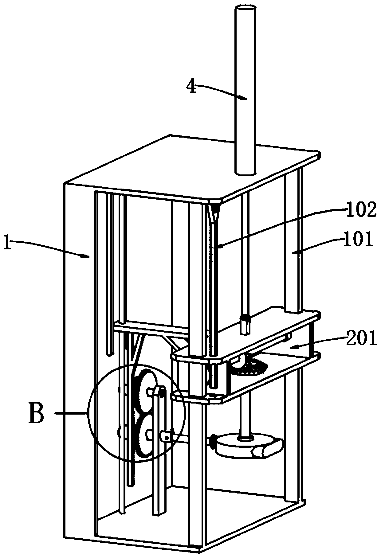
[0032] The present invention provides a device for intermittent rotation and middle opening of glass vases, which includes a rotary opening mechanism 2; The top of mechanism 2 is fixedly connected with the telescoping end of electric cylinder 4 by bolts, and the interior rear side end of frame body 1 is also equipped with vase intermittent rotation mechanism 3, and vase intermittent rotation mechanism 3 is connected with rotary opening mechanism 2 transmission.

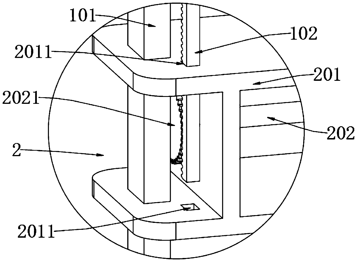
[0033] Wherein, the rotary drilling mechanism 2 includes an adjustment frame 201, a horizontal shaft 202, a side gear 2021, a horizontal bevel gear 2022, a hole shaft 203, a vertical bevel gear 2031 and a hole opening head 2032, and the adjustment frame 201 is slidably installed on the frame On the front guide column 101 at the front end of the inner side of the body 1, and the middle of the adjustment frame 201 is inlaid with a horizontal shaft 202, and th...

Embodiment 2

[0036] On the basis of embodiment 1, as attached Figure 4-6 , attached Figure 8 And attached Figure 9 Shown:

[0037] The present invention provides an intermittent rotation and middle opening device for glass vases. The vase intermittent rotation mechanism 3 includes an intermittent rotation shaft 301, an intermittent rotation gear 3013, a linkage shaft 302, an incomplete gear 3021, a ratchet device 3022 and a support frame 303. The intermittent rotation gear 3013 is clamped on the intermittent rotating shaft 301 and can mesh with the locking teeth on the incomplete gear 3021, and the incomplete gear 3021 is clamped on the linkage shaft 302, and the rear end of the linkage shaft 302 is also clamped with a ratchet device 3022 , and the front ends of the linkage shaft 302 and the intermittent rotating shaft 301 are respectively supported and fixed by the support frame 303 .

[0038] Wherein, the front end side of the intermittent rotating shaft 301 is also provided with a s...


PUM


Abstract

The invention provides an intermittent rotation and middle punching device for a glass vase, belongs to the technical field of punching in the central part of the vase, and solves the problem that thepunching efficiency in the central part of the glass vase is low. The device comprises a rotary punching mechanism, wherein the rotary punching mechanism is slidably mounted at the front side end ofthe interior of a frame body, the top end of the rotary punching mechanism is fixedly connected with the telescopic end of an electric cylinder through a bolt, a vase intermittent rotation mechanism is arranged at the rear side end of the interior of the frame body and is in transmission connection with the rotary punching mechanism. According to the device, an adjusting frame is driven by the electric cylinder to move downwards, so that a transverse shaft rotates under the action of a side gear and a fixed rack rod; a punching head is downwards inserted into the center of the glass vase whilethe punching head is rotating; and when the adjusting frame moves upwards, clamping teeth at the bottom side end of a vertical connecting rod drive a whole ratchet gear to rotate by one circle, and an intermittent rotation gear is driven by the clamping teeth of the upper half-circle of the incomplete gear to rotate by semi-circle, thereby realizing the overturning of the glass vase.

Description

technical field [0001] The invention belongs to the technical field of hole opening in the middle of a vase, and more specifically relates to a device for intermittent rotation and hole opening in the middle of a glass vase. Background technique [0002] With the continuous improvement of people's living standards, most people like to plant flowers in indoor flowerpots or vases. Traditional flowerpots can be divided into ceramics, plastics, etc. The color of ceramic and plastic vases is relatively single, and the volume of flowerpots The large area covers a wide area, so people usually choose glass vases with different colors. The workers insert the flowers directly into the glass vase, and the water in the glass vase keeps in contact with the roots of the flowers, which will cause the roots of the flowers to rot and stink. Therefore, glass vase manufacturers generally open holes in the middle of the glass vase, (the water in the glass vase will not flow out of the hole afte...

Claims


Application Information

Patent Timeline
IPC IPC(8): B28D1/14B28D7/04
CPCB28D1/146B28D7/04
Inventor 秦胜
Owner 秦胜
Why Eureka
Try Eureka