Optical film, production method thereof, polarizer, and image display device
A technology of optical film and manufacturing method, which is applied in the direction of chemical instruments and methods, optics, optical components, etc., can solve problems such as unevenness and display characteristic decline, and achieve the effects of excellent adhesion, no adhesion, and no optical defects
- Summary
- Abstract
- Description
- Claims
- Application Information
AI Technical Summary
Problems solved by technology
Method used
Image


Examples
Embodiment 1
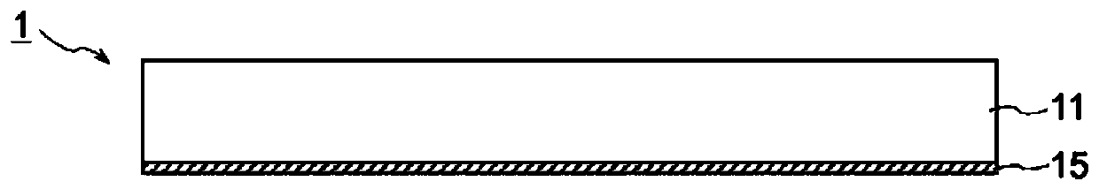
[0135] An optical film was produced using a film manufacturing apparatus equipped with a melt extrusion film forming apparatus, a gravure coater, a tenter type simultaneous biaxial stretching apparatus, and a take-up apparatus. As the acrylic resin, pellets of the same imidized MS resin (glass transition temperature: 120° C.) used in the production of “transparent protective film 1A” described in JP-A-2017-26939 Example were used. material. The acrylic resin was melt-extruded from a T die to form a film with a thickness of 160 μm, and the above-mentioned composition was coated on one side of the film with a wet thickness of about 9 μm by a gravure coater. The biaxial stretching tenter was stretched to 2 times in the longitudinal direction (MD) and the width direction (TD), respectively, to obtain an optical film having an easy-slip layer with a thickness of 50 nm on one side of an acrylic film with a thickness of 40 μm.
Embodiment 2~4 and comparative example 1、2
[0137] An optical film was obtained in the same manner as in Example 1 except that the coating thickness of the composition for forming an easily slippery layer was changed. The thickness (after stretching) of the slippery layer is shown in Table 2.
Embodiment 5、6 and comparative example 3~5
[0139] The furnace temperature (stretching temperature) at the time of tenter stretching was changed as shown in Table 2. An optical film was obtained in the same manner as in Example 1 except that the stretching temperature was changed.
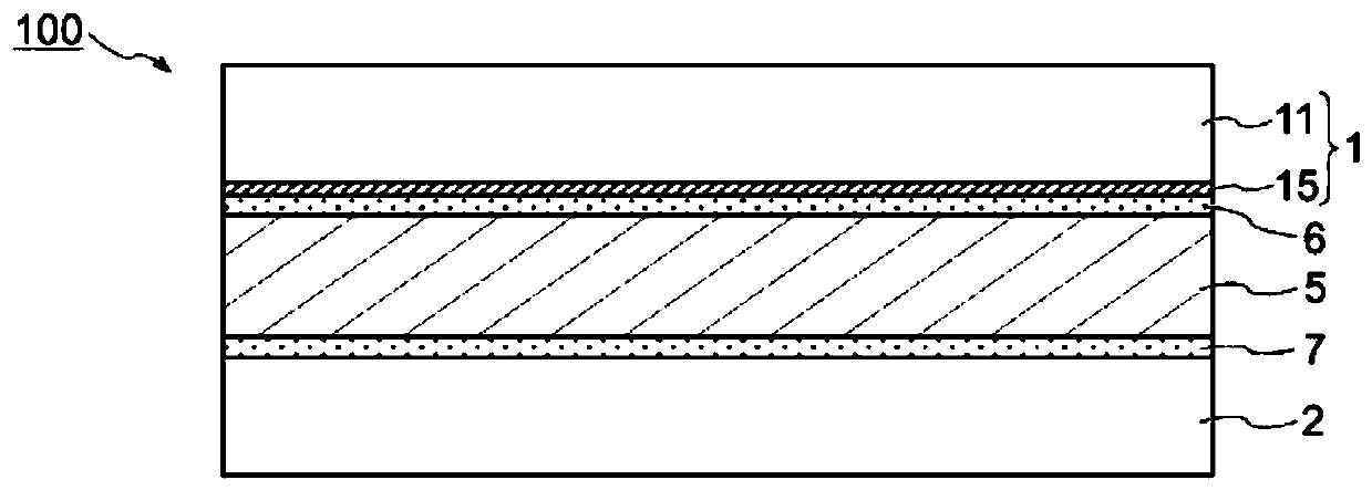
[0140] [Production of polarizing plate]
[0141] (production of polarizer)
[0142] A long roll of a polyvinyl alcohol (PVA)-based resin film ("PE4500" manufactured by Kuraray Co., Ltd.) with a thickness of 45 μm was stretched unidirectionally in the longitudinal direction by a roll stretching machine so that it was 5.9 times the longitudinal direction. Transported in the order of the swelling bath, dyeing bath, crosslinking bath 1, crosslinking bath 2, and cleaning bath shown in Table 1, dried at 70° C. for 5 minutes, and produced a polarizer with a thickness of 18 μm. The iodine concentration and the potassium iodide concentration in the dyeing bath were adjusted so that the single sheet transmittance of the polarizer became 43.4%.
[0...
PUM
| Property | Measurement | Unit |
|---|---|---|
| thickness | aaaaa | aaaaa |
| particle size | aaaaa | aaaaa |
| thickness | aaaaa | aaaaa |
Abstract
Description
Claims
Application Information
 - R&D
- Intellectual Property
- Life Sciences
- Materials
- Tech Scout
- Unparalleled Data Quality
- Higher Quality Content
- 60% Fewer Hallucinations
Browse by: Latest US Patents, China's latest patents, Technical Efficacy Thesaurus, Application Domain, Technology Topic, Popular Technical Reports.
© 2025 PatSnap. All rights reserved.Legal|Privacy policy|Modern Slavery Act Transparency Statement|Sitemap|About US| Contact US: help@patsnap.com