
Power distribution area power distribution system with distributed energy storage devices and control method thereof

A technology for distributed energy storage and power distribution systems, applied in circuit devices, harmonic reduction devices, system integration technologies, etc., can solve the problems of small margins that cannot meet power supply needs and energy saving, and improve the level of on-site consumption , the effect of smoothing power fluctuations, strong compatibility and flexibility

Pending Publication Date: 2020-07-24
NARI TECH CO LTD +2
View PDF4 Cites 7 Cited by
  • Summary
  • Abstract
  • Description
  • Claims
  • Application Information

AI Technical Summary

Problems solved by technology

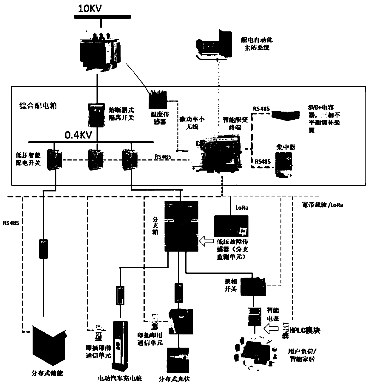
[0004] Purpose of the invention: In view of the fact that the transformers and lines in some existing distribution stations have a small margin during construction and cannot meet the needs of power supply and energy saving issues, the first purpose of the present invention is to provide a distribution station with a distributed energy storage device District distribution system

Method used

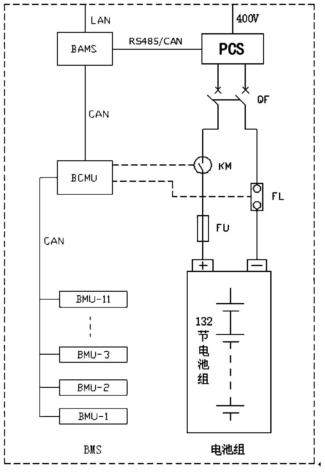
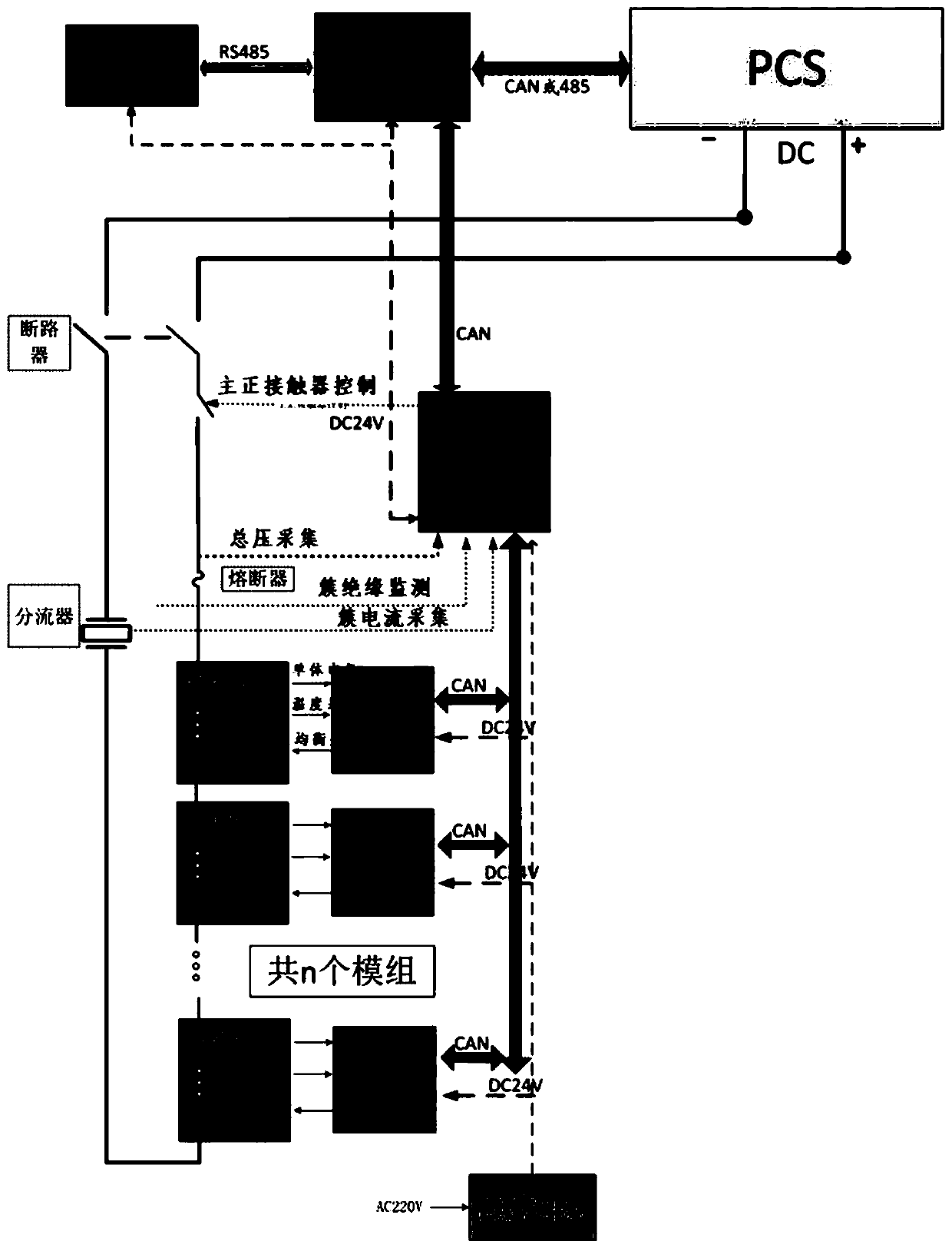

Image

  • Power distribution area power distribution system with distributed energy storage devices and control method thereof
  • Power distribution area power distribution system with distributed energy storage devices and control method thereof
  • Power distribution area power distribution system with distributed energy storage devices and control method thereof

Examples


Embodiment Construction

[0032] In order to describe the technical solution disclosed in the present invention in detail, further elaboration will be made below in conjunction with the accompanying drawings and specific embodiments.

[0033] With the improvement of people's living standards due to economic development and the increase of electricity load, some distribution stations in many areas of our country usually operate normally, but there are several peak loads in a year, which will approach or even exceed the capacity of existing transformers and lines. , leading to tripping and power failure, reducing the reliability of power supply. This has brought great difficulties to the power supply service and operation management of the power grid company. At present, the main solution is to increase the capacity of the distribution station area. However, this method has a long construction period and the disadvantages of low equipment utilization are also obvious.

[0034]In order to solve the above...


PUM


Abstract

The invention discloses a power distribution area power distribution system with distributed energy storage devices and a control method thereof. A transformer in the power distribution system is connected with the distributed energy storage devices through a low-voltage power distribution switch. The energy storage system comprises an energy storage converter PCS, a battery system, a battery management system BMS, an intelligent controller and a communication module. The direct current side of the energy storage converter PCS is connected with a battery pack, the alternating current side of the energy storage converter PCS is connected with a transformer area low-voltage bus and keeps communication with the TTU of the power distribution transformer area where the energy storage converterPCS is located, and all the energy storage devices are integrated in one JP cabinet to achieve better management and configuration. According to the power distribution area power distribution system,the distributed energy storage devices are arranged in the power distribution system, so that power failure under the conditions of periodicity, sudden large loads and the like is prevented, the overload conditions of lines and transformers are prevented, the investment of primary equipment of a power distribution network is reduced, and the utilization rate of the equipment is increased.

Description

technical field [0001] The invention belongs to the application of power energy storage devices in power distribution systems, and in particular relates to a power distribution system in a power distribution station with distributed energy storage devices. Background technique [0002] With the improvement of people's living standards and economic development, the power load increases, causing some distribution stations in many areas to operate normally, but there are several peak loads in a year, which will approach or even exceed the capacity of existing transformers and lines. Lead to tripping and power failure, reducing the reliability of power supply. It has brought great difficulties to the power supply service and operation management of the power grid company. At present, the main solution is to increase the capacity of the distribution station area. However, this method has a long construction period and the disadvantages of low equipment utilization are also obvio...

Claims


Application Information

Patent Timeline
Patent Type & Authority Applications(China)
IPC IPC(8): H02J3/46H02J3/32H02J3/26H02J3/01H02J13/00
CPCH02J3/46H02J3/32H02J3/26H02J3/01Y04S10/12Y04S10/14Y02E40/40Y02E40/50Y02E40/70Y02E60/00
Inventor 赵景涛蒋国栋谢丰宋飞黄丹傅强葛卫梁陈娜梁顺尹宏旭黄堃李延满
Owner NARI TECH CO LTD
Learn More