
Textile fabric uniform drying device based on reciprocating motion

A drying device and textile fabric technology, applied in the field of textile fabrics, can solve problems affecting textiles, moisture, and long drying time of fabrics, etc.

Inactive Publication Date: 2020-07-24
陈成祥
View PDF5 Cites 12 Cited by
  • Summary
  • Abstract
  • Description
  • Claims
  • Application Information

AI Technical Summary

Problems solved by technology

[0003] Traditional textiles evaporate the moisture inside the textiles by drying them in the sun. With the development of the technology, a large number of dryers have appeared. Although the general dryers are large in size and can increase the amount of textiles dried, but Because the humidity of each roll of textiles is different, this leads to different drying effects of each roll of textiles, and it is likely to burn some textiles, affecting the quality of textiles. The traditional machine for drying textile fabrics has a single structure and simple functions. , the drying time of the cloth is long, the efficiency is low, and the drying effect is uneven after drying, and there are over-drying or still wet phenomena in some places, and it is not easy to collect, and a large number of wrinkles are prone to appear during collection, which increases the post-processing difficulty

Method used


Image

  • Textile fabric uniform drying device based on reciprocating motion
  • Textile fabric uniform drying device based on reciprocating motion
  • Textile fabric uniform drying device based on reciprocating motion

Examples


Embodiment Construction

[0028] The following will clearly and completely describe the technical solutions in the embodiments of the present invention with reference to the accompanying drawings in the embodiments of the present invention. Obviously, the described embodiments are only some, not all, embodiments of the present invention. Based on the embodiments of the present invention, all other embodiments obtained by persons of ordinary skill in the art without making creative efforts belong to the protection scope of the present invention.

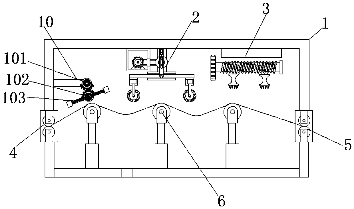
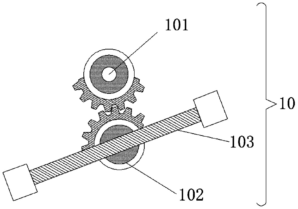
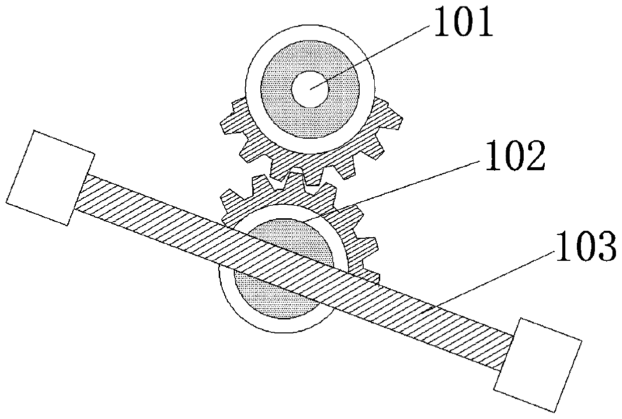
[0029] see Figure 1-8, a textile fabric uniform drying device based on reciprocating motion, comprising a device main body 1, a beating device 10, a rolling drying device 2 and a reciprocating heating device 3 are arranged inside the device main body 1, and a main deflection device is arranged inside the beating device 10 The gear 101 and the sub-deflection gear 102, the sub-deflection gear 102 is provided with a beating bar 103, after the textile fabric pass...


PUM


Abstract

The invention relates to the technical field of textile fabrics, and discloses a textile fabric uniform drying device based on reciprocating motion. The textile fabric uniform drying device comprisesa device main body, wherein a beating device, a rolling drying device and a reciprocating heating device are arranged inside the device main body; a primary deflection gear and a secondary deflectiongear are arranged inside the beating device; a beating rod is arranged on the secondary deflection gear; and air jet holes are connected below a motion slide block. During use of the textile fabric uniform drying device based on reciprocating motion, textile fabrics are placed into the device main body from a fabric inlet, undried fabrics are overlapped on lifting drums to be sequentially transported to the beating device, the beating device works, the primary deflection gear rotates to drive the secondary deflection gear meshed below the primary deflection gear to start reciprocating motion,and then the beating rod arranged on the secondary deflection gear is driven to perform reciprocating beating in order to beat water drops on the undried fabrics, so that the situation that drying cannot be performed in subsequent procedures due to over high water content is avoided.

Description

technical field [0001] The invention relates to the technical field of textile fabrics, in particular to a reciprocating motion-based uniform drying device for textile fabrics. Background technique [0002] Fabric is the material used to make clothing. As one of the three elements of clothing, fabric can not only interpret the style and characteristics of clothing, but also directly affect the color and shape of clothing. In the textile process, drying is essential In the link, only after drying the tie-dyed fabric can it be put into the later process. [0003] Traditional textiles evaporate the moisture inside the textiles by drying them in the sun. With the development of the technology, a large number of dryers have appeared. Although the general dryers are large in size and can increase the amount of textiles dried, but Because the humidity of each roll of textiles is different, this leads to different drying effects of each roll of textiles, and it is likely to burn so...

Claims


Application Information

Patent Timeline
Patent Type & Authority Applications(China)
IPC IPC(8): F26B13/08F26B13/10F26B13/18F26B25/02F26B21/00F26B13/28
CPCF26B13/08F26B13/10F26B13/183F26B13/28F26B21/004F26B25/02
Inventor 陈成祥
Owner 陈成祥
Learn More