
Conveying roller supporting beam pressing and fixing device and pressing and fixing method thereof

A technology of fixing device and fixing method, which is applied in the direction of transportation, packaging, roller table, etc. It can solve problems such as left and right shaking of the roller table, collision with conveying rollers, potential safety hazards, etc., to ensure connection stability, avoid left and right shaking, and save effort to press down Effect

Active Publication Date: 2021-06-08
MAANSHAN IRON & STEEL CO LTD
View PDF9 Cites 0 Cited by
  • Summary
  • Abstract
  • Description
  • Claims
  • Application Information

AI Technical Summary

Problems solved by technology

The conveying roller support beam has the following defects during use: 1. During the use of the support beam, due to the transportation of the steel billet in the roller table, it will inevitably cause the vibration of the roller table. The long-term vibration will cause the fixing bolts of the support beam base to loosen, resulting in There is a gap between the beam base and the concrete pile under the roller table. As time goes on, the gap becomes larger and larger, and the roller table will shake left and right in the direction of travel. If the shaking angle is too large, the red hot steel billet will escape from the roller table, causing safety hazards ; 2. The support beam carries a lot of equipment, and the dummy bar storage device is installed on the support beam. The dummy bar will cause the roller table to shake left and right in the direction of travel during the process of lowering and lifting the dummy bar. Regular shape, there will be impact on the conveyor roller during the process of traveling in the roller table, and the irregular vibration of the roller table will also cause the problems described in 1; 3. In order to ensure normal production, when the support beam fixing device is damaged and tilted, it is necessary to Re-fixing the base is not conducive to efficient management of equipment; 4. Every time when one side of the support beam base of the conveyor roller is tilted, a large-section steel billet needs to be placed on the roller table with a crane, and the tilted side is pressed down. During maintenance, the roller There are many maintenance personnel on the road, and there are potential safety hazards in hoisting steel billets on the roller table; 5. Due to the design defect of the conveyor roller support beam fixing device, that is, only one pressing plate and bolts are used for fixing, resulting in poor overall stability of the fixing device; 6. Due to The location of the fixing device is not conducive to the occupation of maintenance workers, and there are potential safety hazards for personnel in regular maintenance

Method used


Image

  • Conveying roller supporting beam pressing and fixing device and pressing and fixing method thereof
  • Conveying roller supporting beam pressing and fixing device and pressing and fixing method thereof
  • Conveying roller supporting beam pressing and fixing device and pressing and fixing method thereof

Examples


Embodiment Construction

[0031] Below with reference to the accompanying drawings, through the description of the embodiments, the specific embodiments of the present invention, such as the shape, structure, mutual position and connection relationship between the various parts, the role and working principle of the various parts, etc., will be further described. Detailed instructions:

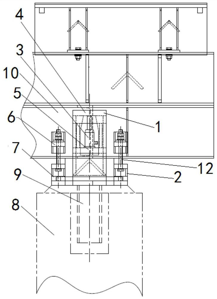
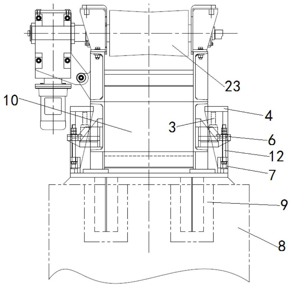
[0032] as attached figure 1 - attached Figure 7bShown, the present invention is a kind of conveying roller supporting beam depressing and fixing device, described conveying roller supporting beam depressing and fixing device comprises depressing part 1, fixing part 2, jack 3, depressing part 1 comprises depressing The upper base 4 and the lower base 5 are pressed down. The fixing part 2 includes a fixed upper assembly 6 and a lower fixed assembly 7. The upper base 4 is set as a structure that can be welded with the embedded part 9 on the support beam base 8, The lower base 5 is configured as a structure that can be ...


PUM


Abstract

The invention provides a conveying roller supporting beam pressing and fixing device applied in the technical field of continuous casting production. The invention also relates to a conveying roller supporting beam pressing and fixing method. The described conveying roller supporting beam pressing and fixing device The pressing part (1) includes pressing down the upper base (4) and pressing down the lower base (5), the fixing part (2) includes fixing the upper assembly (6) and fixing the lower assembly (7), pressing down the upper base (4) It is arranged as a structure capable of being welded with the embedded part (9) on the support beam base (8), and the lower base (5) is set as a structure capable of welding with the support beam body (10). The conveying roller of the present invention The support beam depressing and fixing device and its depressing and fixing method can facilitate the support beam depressing, facilitate the fixing of the support beam body, ensure the reliable arrangement of the support beam, reduce the possibility of easy vibration during use, and increase equipment Stability, reducing safety hazards for maintenance personnel.

Description

technical field [0001] The invention belongs to the technical field of continuous casting production, and more specifically relates to a device for pressing down and fixing a supporting beam of a conveying roller, and also relates to a method for pressing and fixing the supporting beam of a conveying roller. Background technique [0002] In prior art continuous casting production, the conveyor roller support beam is mainly used to support devices such as the conveyor roller, the dummy rod storage rack, the dummy rod, the conveyor roller, and the water cooling plate of the conveyor roller bearing seat. The device is placed on the support beam base (concrete pile) under the roller table, and the two sides of the support beam are fixed by simple two pressure plates. The conveying roller support beam has the following defects during use: 1. During the use of the support beam, due to the transportation of the steel billet in the roller table, it will inevitably cause the vibratio...

Claims


Application Information

Patent Timeline
Patent Type & Authority Patents(China)
IPC IPC(8): B65G13/11B22D11/12B22D11/128
CPCB22D11/12B22D11/1287B65G13/11
Inventor 戴本俊王伟峰徐林林
Owner MAANSHAN IRON & STEEL CO LTD
Learn More