
Bendable steel bar cutting device for building construction

A technology of cutting device and steel bar, which is applied in manufacturing tools, metal processing, metal processing equipment, etc., can solve the problems of inability to straighten ribbed steel bars, straightening blocks, fast wear of traction rollers, complicated control lines, etc. Straight cutting efficiency, improved fixed-length accuracy, and simple operation

Inactive Publication Date: 2020-07-24
郑林林
View PDF0 Cites 6 Cited by
  • Summary
  • Abstract
  • Description
  • Claims
  • Application Information

AI Technical Summary

Problems solved by technology

At present, the control circuit of ordinary steel bar straightening and cutting machine is complicated, and the faults are frequent. While realizing the straightening and cutting functions, the dimensional accuracy and work efficiency of the processed steel bar need to be improved. Many straightening machines cannot take into account the length when designing Accuracy and straightening speed, for example, the hydraulic straightening and cutting machine has the problem of a long shortest working range; the current steel bar straightening mechanism mostly adopts the straight block rotary hub type, and the disadvantage of the straight block rotary hub type straightening machine is: in the whole During the straightening process, the steel bar is sliding friction in the straightening block, the surface of the steel bar is scratched, the straightening block and the traction roller wear quickly, and they are vulnerable parts, and the ribbed steel bar cannot be straightened at all; during the cutting process of the steel bar , due to the shearing and extrusion of the steel bar by the cutter, the resulting fracture section is uneven and mostly horseshoe-shaped. The horseshoe-shaped acute angle at the steel bar section is a safety hazard at the construction site, and it cannot meet special requirements for the steel bar fracture section. For housing construction, traditional blades will not be able to process this section

Method used


Image

  • Bendable steel bar cutting device for building construction
  • Bendable steel bar cutting device for building construction
  • Bendable steel bar cutting device for building construction

Examples


Embodiment Construction

[0046] The following will clearly and completely describe the technical solutions in the embodiments of the application with reference to the drawings in the embodiments of the application. Apparently, the described embodiments are only some of the embodiments of the application, not all of them. The following description of at least one exemplary embodiment is merely illustrative in nature and in no way serves as any limitation of the application, its application or uses. Based on the embodiments in this application, all other embodiments obtained by persons of ordinary skill in the art without creative efforts fall within the protection scope of this application.

[0047] It should be noted that the terminology used here is only for describing specific implementations, and is not intended to limit the exemplary implementations according to the present application. As used herein, unless the context clearly dictates otherwise, the singular is intended to include the plural, a...


PUM


Abstract

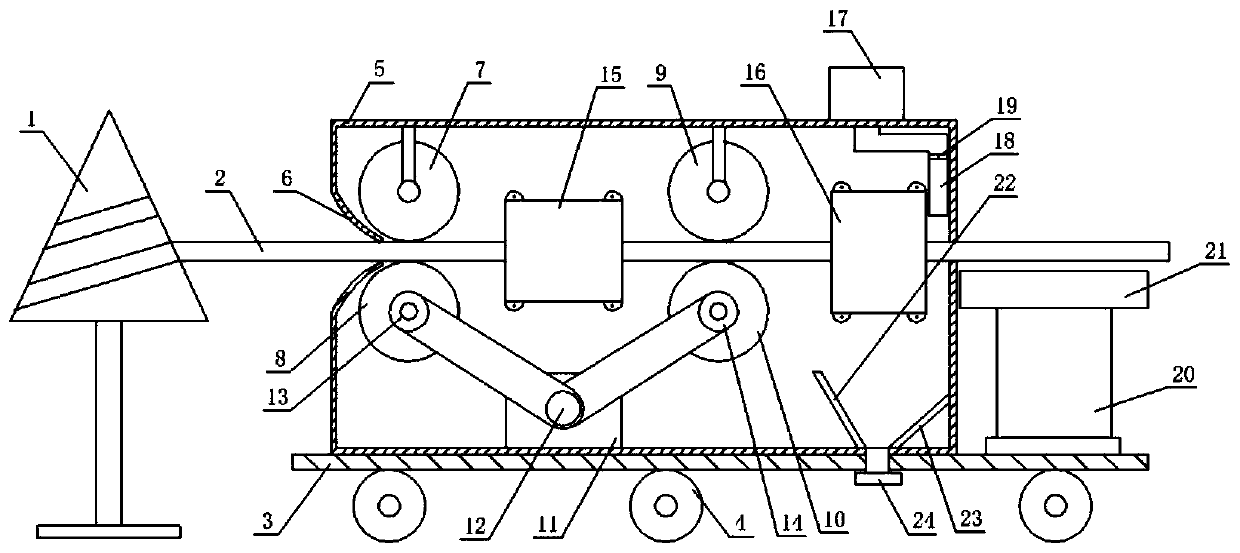
The invention discloses a bendable steel bar cutting device for building construction. The bendable steel bar cutting device for building construction comprises a fixing support, an outer shell fixedly arranged on the fixing support, a steel bar inlet formed in the front side of the outer shell, a steel bar outlet formed in the front side of the outer shell, a bearing mechanism fixed to the fixingsupport and positioned at the steel bar outlet, a traction mechanism, a straightening mechanism, a cutting mechanism and a cleaning and collecting mechanism, wherein the traction mechanism, the straightening mechanism, the cutting mechanism and the cleaning and collecting mechanism are separately arranged in the outer shell; and the straightening mechanism comprises a fixing frame rotatably connected inside the outer shell, two supporting shafts oppositely arranged on the two sides of the fixing frame and used for a steel bar to penetrate through, straightening rollers rotatably arranged in the fixing frame and balance iron fixed on the top of the inner side of the fixing frame. According to the bendable steel bar cutting device for building construction, the steel bar straightening and cutting efficiency can be improved, both the length precision and the straightening speed are taken into consideration, pressed marks on the surface of the steel bar caused by the fact that the straightening rollers reversely bend the steel bar are eliminated, and the section of the cutting fracture of the steel bar is flat and smooth.

Description

technical field [0001] The invention relates to the field of steel structure processing equipment, in particular to a bendable steel bar cutting device used in house construction. Background technique [0002] Reinforcement refers to steel for reinforced concrete and prestressed reinforced concrete, which is circular in cross-section and sometimes square with rounded corners. Steel bars for reinforced concrete refer to the straight or coiled steel used for reinforced concrete reinforcement. Its shape is divided into two types: smooth round steel bar and deformed steel bar. The delivery state is straight bar and coiled round. Light round steel bars are actually small round bars and discs of ordinary low carbon steel. Deformed bars are ribbed bars on the surface, usually with 2 longitudinal ribs and transverse ribs evenly distributed along the length. The shape of the transverse rib is spiral, herringbone and crescent. The nominal diameter of a deformed steel bar is equival...

Claims


Application Information

Patent Timeline
Patent Type & Authority Applications(China)
IPC IPC(8): B21F11/00B21F23/00B21F1/02B21C51/00B08B15/02
CPCB08B15/02B21C51/00B21F1/026B21F11/00B21F23/00
Inventor 郑林林李磊
Owner 郑林林
Learn More