
Computer vision measurement system

A computer vision and measurement system technology, applied in the direction of measuring devices, instruments, optical devices, etc., can solve the problems of not adapting to the needs of automation development, achieve long-term stable measurement, appropriate accuracy, and improve reliability

Pending Publication Date: 2020-07-21
谢登航 +2
View PDF6 Cites 3 Cited by
  • Summary
  • Abstract
  • Description
  • Claims
  • Application Information

AI Technical Summary

Problems solved by technology

[0003] With the development of production, measurement technology, as a means of guaranteeing production quality and efficiency, is increasingly showing its importance. For the measurement of the size of workpiece machining parts, the traditional manual measurement method is no longer suitable for the needs of automation development, so a computer is needed. The visual measurement system improves the above problems

Method used


Image

  • Computer vision measurement system
  • Computer vision measurement system
  • Computer vision measurement system

Examples


Embodiment Construction

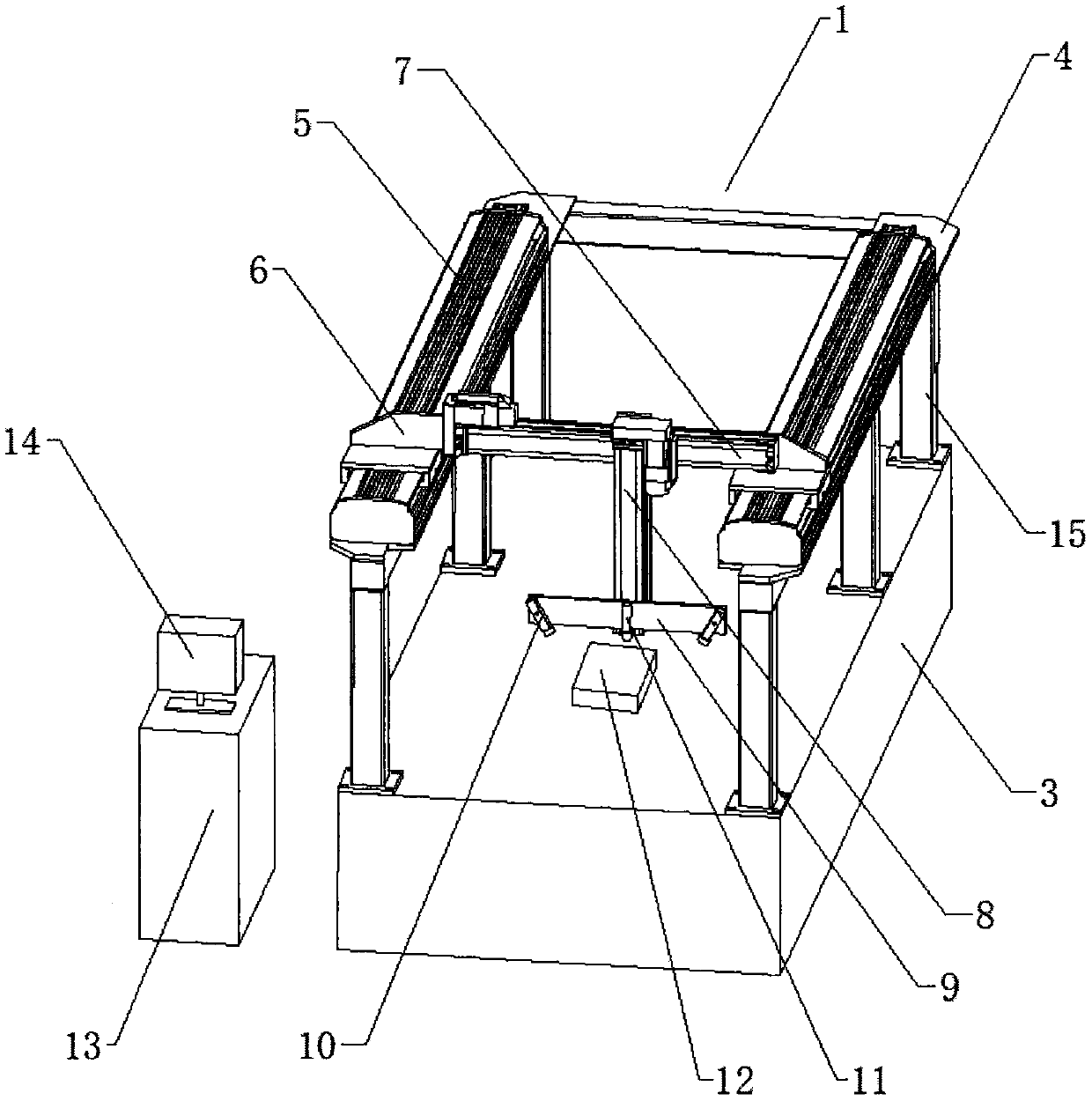
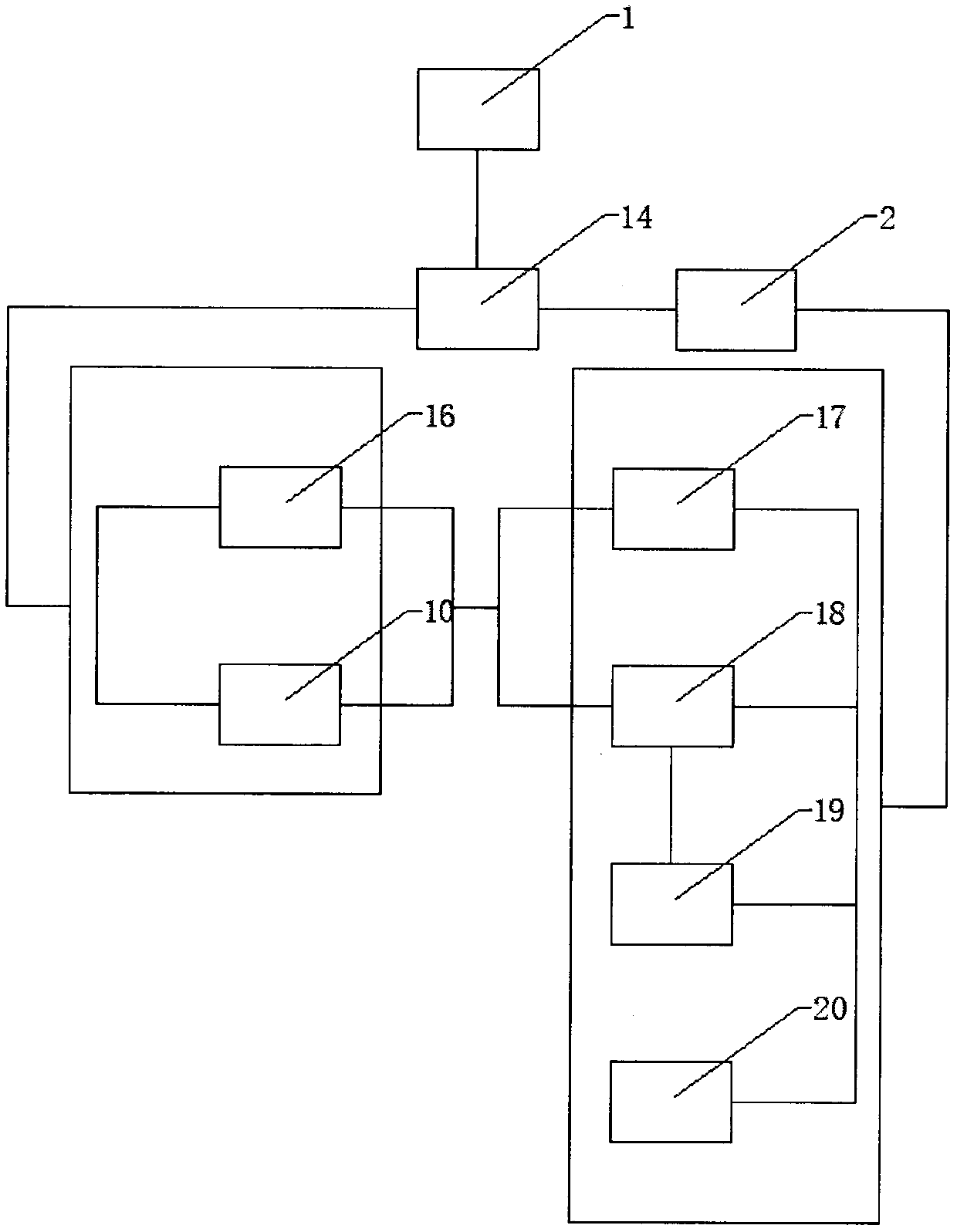
[0027] The following will clearly and completely describe the technical solutions in the embodiments of the present invention in conjunction with the accompanying drawings in the embodiments of the present invention. Obviously, the described embodiments are only a part of the embodiments of the present invention, rather than all the embodiments. The embodiments of the present invention, and all other embodiments obtained by those of ordinary skill in the art without creative work, fall within the protection scope of the present invention.

[0028] See Figure 1-3 , The present invention provides a technical solution:

[0029] A computer vision measurement system includes a hardware system part 1 and a software system part 2. The hardware system part 1 contains a working platform 3. The end of the working platform 3 away from the ground is screwed with a mounting bracket 15, and the mounting bracket 15 is far away from the working platform 3. One end is welded with the screw module...


PUM


Abstract

The invention relates to the technical field of computer measurement, and in particular to a computer vision measurement system. The system comprises a hardware system part and a software system part.The hardware system part comprises a working platform. The end, away from the ground, of the working platform is in screw connection with a mounting bracket. A screw rod module mounting plate is welded at the end, far away from the working platform, of the mounting bracket. The end, far away from the mounting bracket, of the screw rod module mounting plate is in screw connection with an X-direction screw rod module. The end, far away from the screw rod module mounting plate, of the X-direction screw rod module is in screw connection with a Y-direction screw rod module mounting plate. A Y-direction screw rod module is connected to the outer wall of the Y-direction screw rod module mounting plate through screws. A Z-direction screw rod module is connected to the end, far away from the Y-direction screw rod module mounting plate, of the Y-direction screw rod module through screws. The computer vision measurement system has the advantages of being high in anti-interference capacity, highin efficiency, appropriate in precision and the like, realizes intelligentization, digitization, miniaturization, networking and multifunction, and has certain popularization value.

Description

Technical field [0001] The present invention relates to the technical field of computer measurement, in particular to a computer vision measurement system. Background technique [0002] Human beings are entering the information age, and computers will increasingly enter almost all fields. On the one hand, more people without professional computer training also need to use computers. On the other hand, the functions of computers are getting stronger and stronger and their use methods are getting more and more complicated. This creates a sharp contradiction between the flexibility of people in conversation and communication and the strict and rigid requirements when using computers. Humans can exchange information with the outside world through vision, hearing, and language, and can express the same meaning in different ways, while computers require programs to be written in strict accordance with various programming languages, and only then can the computer run. In order to enab...

Claims


Application Information

Patent Timeline
IPC IPC(8): G01B11/25
CPCG01B11/2504G01B11/2518G01B11/2545
Inventor 谢登航闫亚哲张云睿
Owner 谢登航
Learn More